Grid-connected inverter grid-connection point voltage dynamic compensation control method

A control method and dynamic compensation technology, applied in the direction of AC network voltage adjustment, reactive power compensation, irreversible DC power input conversion to AC power output, etc., can solve the problem of dynamic voltage change compensation control, increase system investment and maintenance costs , voltage drop and other problems, to achieve the effect of enhancing reliability and stability, improving grid-connected penetration rate, and improving utilization efficiency

Active Publication Date: 2013-11-27
INST OF ELECTRICAL ENG CHINESE ACAD OF SCI
View PDF3 Cites 28 Cited by
  • Summary
  • Abstract
  • Description
  • Claims
  • Application Information

AI Technical Summary

Problems solved by technology

Lead to voltage rise or voltage drop at grid-connected point of photovoltaic power generation system, affecting the penetration rate of photovoltaic power generation system
[0003] On the one hand, the traditional grid voltage control method is to adjust the voltage by installing some additional voltage control equipment, such as dynamic voltage restorer, automatic voltage controller, static synchronous compensator, etc., which greatly increases the investment and maintenance costs of the system , cannot realize the economical and efficient operation of the entire power generation system
[0004] On the other hand, traditional voltage control equipment is based on fixed reactive power (Q) control methods, fixed power factor Control mode, active power-power factor characteristics Control method, steady-state voltage amplitude-reactive power Q-U droop control method, etc. These voltage control strategies are all steady-state voltage control strategies, not dynamic voltage adjustment strategies, so they cannot effectively control dynamic voltage changes. Realize Compensation Control
At the same time, the above traditional voltage control strategies cannot achieve precise control of the voltage, and the system compensation capacity required by these control strategies is relatively large

Method used


Image

  • Grid-connected inverter grid-connection point voltage dynamic compensation control method
  • Grid-connected inverter grid-connection point voltage dynamic compensation control method
  • Grid-connected inverter grid-connection point voltage dynamic compensation control method

Examples


Embodiment Construction

[0021] The present invention will be further described below in conjunction with the accompanying drawings and specific embodiments.

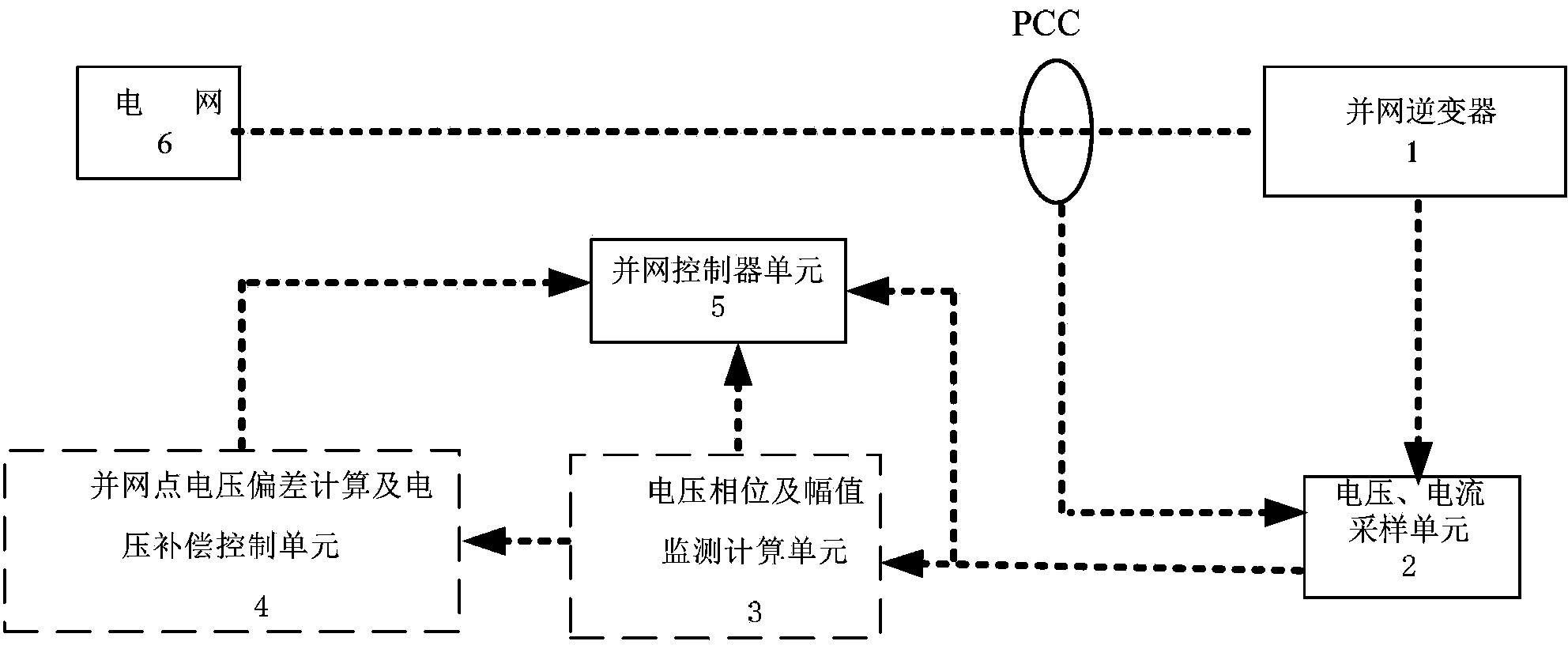
[0022] Such as figure 1 As shown, the grid-connected inverter system in the three-phase microgrid includes a grid-connected inverter 1, a voltage and current sampling unit circuit 2, a voltage phase and amplitude monitoring calculation unit 3, a grid-connected point voltage deviation calculation and A voltage compensation control unit 4, and a grid-connected current control unit 5.

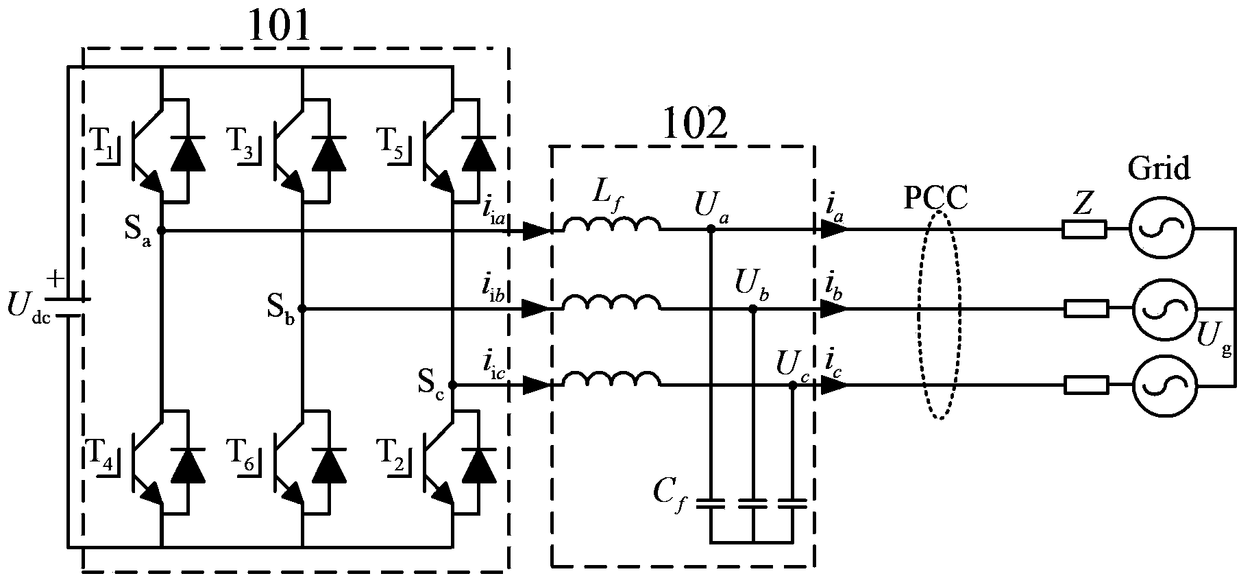
[0023] Such as figure 2 As shown, grid-connected inverter 1 includes DC bus power supply U dc , a three-phase inverter bridge 101, and a three-phase LC filter 102.

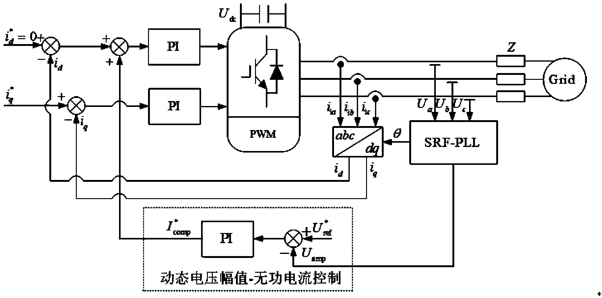
[0024] Such as image 3 As shown, the grid-connected inverter grid-connected point voltage dynamic compensation control method in the three-phase microgrid of the present invention is as follows:

[0025] Step 1: Acquisition of the voltage and current sampling unit circuit mainly completes the ac...


PUM


Abstract

A grid-connected inverter grid-connection point voltage dynamic compensation control method, namely, a dynamic voltage amplitude wattless current IQ (U) voltage compensation control method is provided. When the voltage of a grid-connection point of a grid-connected inverter rises and exceeds the limitation on voltage deviation posed by power grid standards, the grid-connected inverter is controlled and is made to absorb a certain wattless power, such that the voltage of the grid-connection point can be restored to be in a voltage deviation range; and when the voltage of the grid-connection point voltage drops, the grid-connected inverter is controlled and is made to generate a certain wattless power, such that the voltage of the grid-connection point can be restored to be in a normal voltage range.

Description

technical field [0001] The invention relates to a method for dynamically compensating and controlling the grid-connected point voltage of a grid-connected inverter. Background technique [0002] Solar energy is a typical renewable energy source. Due to the influence of ambient temperature, sunlight intensity and weather conditions, photovoltaic power generation exhibits large random fluctuations and unpredictable characteristics. In a field test of a project, the maximum power change rate is 20% / min . With the grid-connected operation of large-scale photovoltaic power generation systems, the impact on the power system is also increasing. It will lead to voltage increase or voltage drop at the grid-connected point of the photovoltaic power generation system, which will affect the penetration rate of the photovoltaic power generation system. [0003] On the one hand, the traditional grid voltage control method is to adjust the voltage by installing some additional voltage co...

Claims


Application Information

Patent Timeline
Patent Type & Authority Applications(China)
IPC IPC(8): H02J3/16H02J3/38H02M7/48
CPCY02E40/34Y02E40/30
Inventor 黄欣科王环王一波许洪华
Owner INST OF ELECTRICAL ENG CHINESE ACAD OF SCI
Why Eureka
Try Eureka