A fixture for making a current transformer and a method for making the current transformer

A technology of a current transformer and a manufacturing method, which is applied to inductors, circuits, transformers, etc., can solve the problems of affecting the coplanarity, the displacement of the ring, and the lack of effective guarantee of the coplanarity of the transformer, and achieve the guarantee Coplanarity, the effect of ensuring coplanarity

Active Publication Date: 2016-03-02
MORNSUN GUANGZHOU SCI & TECH
View PDF8 Cites 0 Cited by
  • Summary
  • Abstract
  • Description
  • Claims
  • Application Information

AI Technical Summary

Problems solved by technology

[0011] 1. The co-planarity of the transformer cannot be effectively guaranteed. After the transformer is assembled, it will inevitably touch the primary metal ring piece during the hand-held glue bonding operation and handling process, thereby causing the ring piece to shift or float. High, which affects the coplanarity between the metal ring piece and the skeleton terminal pin; in addition, when the magnetic core glue is baked, the magnetic core glue is heated and expanded, and the primary metal ring piece is displaced by the expansion force, which affects the coplanarity
[0012] 2. During the hand-held dispensing process, the transformer needs to be turned back and forth due to the dispensing position, resulting in a waste of man-hours and affecting work efficiency
[0013] 3. Hand-held glue dispensing cannot accurately control the bonding position and glue volume, and product consistency cannot be guaranteed

Method used


Image

  • A fixture for making a current transformer and a method for making the current transformer
  • A fixture for making a current transformer and a method for making the current transformer
  • A fixture for making a current transformer and a method for making the current transformer

Examples


Embodiment Construction

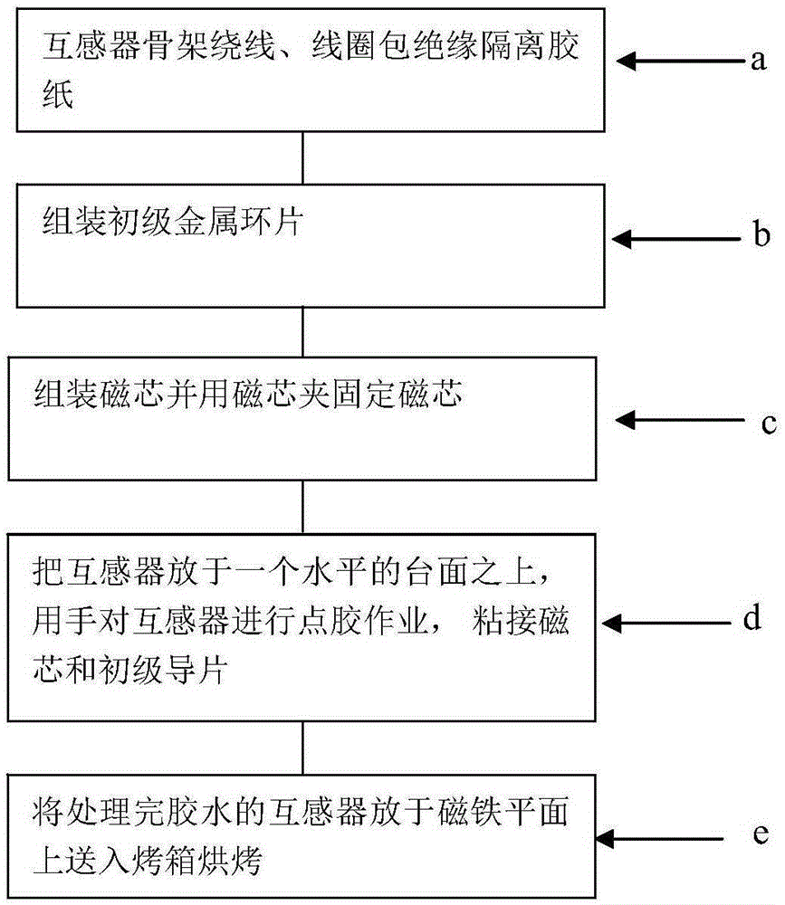
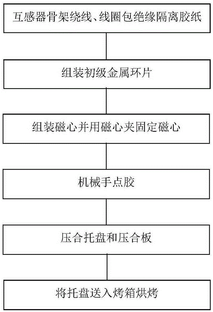
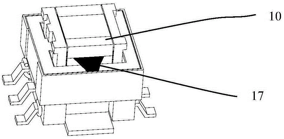
[0056] The model of the current transformer 10 in the preferred embodiment of the present invention is EE5.0. Such as figure 2 Shown, is the method that a kind of current transformer of the present invention is made, comprises the following steps:

[0057] (1). Secondary winding of the transformer skeleton, insulation and isolation tape wrapped in the coil: wind the wire 12 on the skeleton 11, hang the wire up and down on the skeleton terminal, and then wrap a circle of high temperature along the direction of the wire wrap Adhesive paper16.

[0058] (2). Assemble the metal ring piece 14 of the primary coil: Assemble the ring piece 14 on the wire package wrapped with tape.

[0059] (3). Assemble the magnetic core and fix the magnetic core with the magnetic core clamp: put the magnetic core 13 into the wire bag, and fix the magnetic core with the magnetic core clamp 15, and the direction of the magnetic core clamp needs to be uniform.

[0060] (4). Manipulator dispensing: Th...


PUM


Abstract

The invention discloses a fixture for manufacturing a current transformer. The fixture comprises a tray which is used for bearing the current transformer and a laminated plate. A plurality of holes for placing the current transformer are formed in the tray. The area of the laminated plate is equivalent to the area of the tray and the laminated plate fully covers the entire tray. The quick assembling of the current transformer can be realized and the consistency of coplanarity is realized. The invention additionally discloses a manufacturing method of the current transformer. By using the manufacturing method, the reject ration of the current transformer can be reduced and the production efficiency is improved.

Description

technical field [0001] The invention relates to a jig for making a current transformer, and also relates to a method for making a current transformer using the jig. Background technique [0002] In high-frequency switching power supplies, current transformers are usually used to detect the current in the circuit based on control requirements. The working principle of the current transformer is basically the same as that of the transformer. The primary winding N connected in series in the power line 1 (Usually '1' circle) the current i flowing 1 Alternating flux is generated, the induction is generated and the secondary winding N 2 The secondary current i is proportional to the number of turns 2 , by sampling to detect i 2 To achieve the purpose of circuit control. At present, the SMD transformer model EE5.0 commonly used in the industry has the characteristics of small size, large detection current, and relatively simple structure, and is widely used in switching power ...

Claims


Application Information

Patent Timeline
Patent Type & Authority Patents(China)
IPC IPC(8): H01F41/00H01F38/28
Inventor 谢赤述向宇峰
Owner MORNSUN GUANGZHOU SCI & TECH
Why Eureka
Try Eureka