Brake assembly of mute tubular motor

A tubular motor and brake component technology, applied in the field of brake components, can solve the problems of slow start, large brake disc, long braking time, etc., and achieve the effects of easy processing, sensitive braking and simple structure

Inactive Publication Date: 2014-03-05
NINGBO HAIYU ELECTROMECHANICAL
View PDF7 Cites 5 Cited by
  • Summary
  • Abstract
  • Description
  • Claims
  • Application Information

AI Technical Summary

Problems solved by technology

[0005] 2. In order to provide sufficient friction, the brake disc connected to the motor shaft must be large
This will inevitably increase the inertia of the motor shaft, slow start, long braking time, and will cause vibration and noise to the tubular motor when rotating at high speed
[0006] 3. Due to the long-term use of the brake disc, the wear will occur. Although the spring can be stretched to make up the gap between the brake disc and the armature, but in this case, the thrust of the spring acting on the armature will change, which will affect the friction during braking. Force, so that the braking time changes
However, the oil-impregnated bearing has high requirements for assembly and cannot bear thrust in the axial direction. The gap caused by the friction between the brake disc and the armature will affect the service life of the oil-impregnated bearing, resulting in poor fit of the oil-impregnated bearing.

Method used


Image

  • Brake assembly of mute tubular motor
  • Brake assembly of mute tubular motor
  • Brake assembly of mute tubular motor

Examples


Embodiment Construction

[0023] Embodiments of the present invention will be further described below in conjunction with the accompanying drawings.

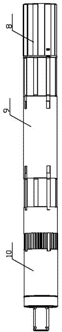
[0024] Such as figure 1 As shown, the motor 9 adopts a coaxial bidirectional output structure, the brake assembly is installed at the tail of the motor 9 , and the reducer assembly 10 and the power output part are installed at the head of the motor 9 .

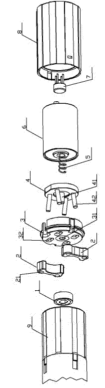
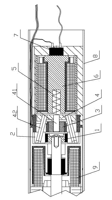
[0025] The brake assembly consists of a brake disc 1, a brake pad 2, a fixed seat 3, an armature seat 4, a spring 5, an electromagnet 6, a bridge stack 7 and a brake sleeve 8, such as figure 2 and image 3 As shown, the brake sleeve 8 is meshed with the casing teeth of the tubular motor 9, and other components are installed inside the brake sleeve. The outside of the brake sleeve 8 is provided with an anti-rotation groove.

[0026] Brake disc 1 is installed on the rotating shaft 11 of motor, fits by key, and is fixed by screw. A friction layer is arranged on the outside of the brake disc, and the fr...


PUM


Abstract

A brake assembly of a mute tubular motor is installed on the tail portion of the tubular motor and comprises a brake disk, brake pads, a fixing base, an armature base, a spring, an electromagnet and a brake cover. The brake cover is meshed with a shell of the tubular motor through teeth, the brake disk is fixed to a rotary shaft of the tubular motor, the brake pads are arranged around the periphery of the brake disk, the spring is installed in a spring groove in the center of the electromagnet, the fixing base is meshed with the inner wall of the brake cover through teeth, one side of the armature base makes contact with the spring, and the spring keeps applying push force to the armature base. A sliding shaft is arranged in the center of the armature base, and the sliding shaft penetrates through a positioning hole of the fixing base. Multiple sets of splayed oblique shafts are arranged on the armature base, and the oblique shafts penetrate through kidney-shaped holes in the fixing base and stretch into oblique holes in the brake pads. The brake assembly is simple in structure and easy to machine; the tubular motor is braked sensitively by a control circuit in the mode that the electromagnet is attracted to the armature base, and the brake pads are further controlled to be unfolded and tightened up through the oblique shafts. Friction plates of the brake assembly are abraded in an integral contact mode, the friction degrees in all positions are the same, and therefore the brake assembly is good in braking effect, longer in service life and low in noise.

Description

technical field [0001] The invention relates to an accessory on a tubular motor, in particular to a brake assembly of a silent tubular motor. Background technique [0002] Tubular motors are widely used as power sources on rolling doors and shutters, and brake components are one of the common accessories of tubular motors. It controls the start and stop of the tubular motor, and can decelerate and lock the high-speed rotating motor. [0003] Most of the existing tubular motor brake components adopt the method of directly attracting the brake pads with electromagnets, as described in the patent number CN200820169167.0 "silent tubular motor brake" and the patent number CN201320033325.0 "braking device for DC tubular motor", including An electromagnet and an armature, the armature is provided with a friction layer, which cooperates with the brake disc installed on the rotating shaft, and it generates friction force through the direct friction of the contact surface, so as to d...

Claims


Application Information

Patent Timeline
Patent Type & Authority Applications(China)
IPC IPC(8): H02K7/102
Inventor 丁道艳王凤军桂慈平丁道栽
Owner NINGBO HAIYU ELECTROMECHANICAL
Why Eureka
Try Eureka