Over-temperature state indication type photovoltaic terminal box based on current measurement

A state indication, volt junction box technology, applied in the field of over-temperature state indication photovoltaic junction box based on current measurement, can solve the problems of unusable and waste of power resources, etc.

Inactive Publication Date: 2014-06-25
SUZHOU BIANFENG ELECTRONICS TECH
View PDF6 Cites 6 Cited by
  • Summary
  • Abstract
  • Description
  • Claims
  • Application Information

AI Technical Summary

Problems solved by technology

The function of the diode is to use its principle of forward conduction and reverse cut-off to prevent reverse charging from damaging the solar cell group, and to prevent a solar cell from being disconnected from causing the entire solar cell group to be unusable.
Since the diode conducts a current of about 10A when it is working, it will cause a large amount of heat accumulation and generate a higher temperature. As the temperature of the diode continues to rise, the resistance in the diode will continue to increase, resulting in more heat generated by the diode. Heat, thus wasting more power resources into a vicious circle

Method used


Image

  • Over-temperature state indication type photovoltaic terminal box based on current measurement

Examples


Embodiment Construction

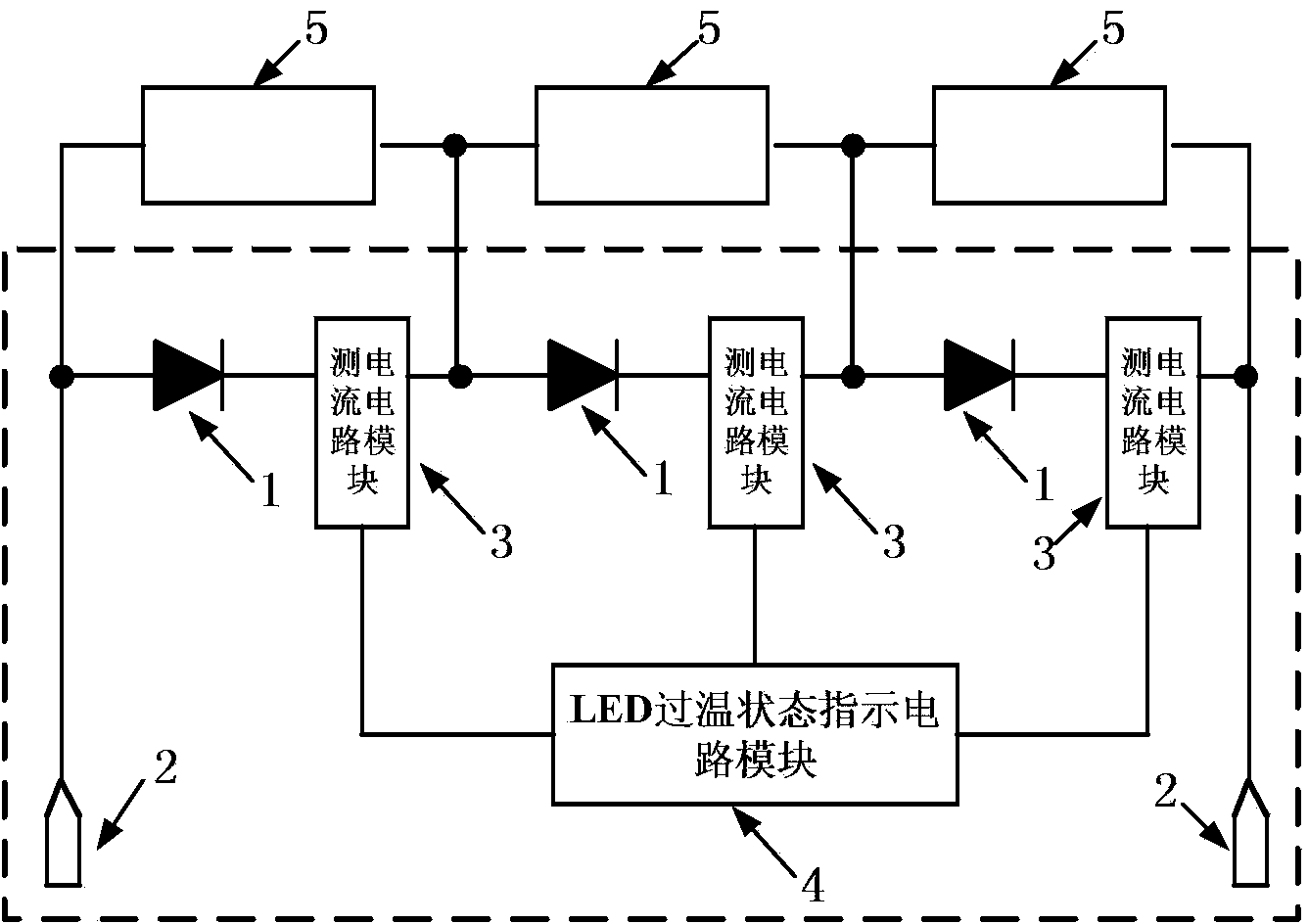
[0010] The specific embodiments of the present invention will be further described below in conjunction with the accompanying drawings.

[0011] Such as figure 1 As shown, the photovoltaic junction box of the present invention includes a diode string 1 , a photovoltaic cable interface 2 , a current measuring circuit module 3 and an LED overtemperature state indicating circuit module 4 in the cavity formed between the upper cover and the base. The diode string 1 includes a plurality of diodes connected in series in the same direction. The number of diodes is the same as the number of photovoltaic cells 5 , and they are connected in parallel with the photovoltaic cells 5 in one-to-one correspondence. Two photovoltaic cable interfaces 2 are respectively connected to both ends of the diode string 1 . A plurality of current measuring circuit modules 3 are respectively connected in series with each diode in the diode string 1 for detecting the current flowing through each diode. T...


PUM


Abstract

The invention discloses an over-temperature state indication type photovoltaic terminal box based on current measurement. The over-temperature state indication type photovoltaic terminal box comprises a diode string, photovoltaic cable interfaces, current measurement circuit modules and an LED over-temperature state indication circuit module. The diode string comprises a plurality of diodes which are connected in series in the same direction, the number of the diodes is the same as the number of photovoltaic batteries, and the diodes are corresponding connected with the photovoltaic batteries in parallel. The two photovoltaic cable interfaces are connected to the two ends of the diode string respectively. Each current measurement circuit module is connected to the corresponding diode in the diode string in series, and the output ends of the current measurement circuit modules are connected with the LED over-temperature state indication circuit module. The LED over-temperature state indication circuit module is connected with the output ends of the current measurement circuit modules and comprises a plurality of LED indication diodes arranged on the surface of an upper cover of the photovoltaic terminal box. When current measurement circuits detect that the current passing through the diodes is excessively high, the LED indication diodes are controlled not to be in the over-temperature abnormal state, and monitoring and warning of the temperature of the photovoltaic terminal box are achieved.

Description

technical field [0001] The invention relates to the field of photovoltaic power generation, in particular to a photovoltaic junction box used in a photovoltaic power generation system, in particular to a photovoltaic junction box with over-temperature status indication based on current measurement. Background technique [0002] In the electrical connection technology of a photovoltaic power generation system, a photovoltaic junction box is usually used to realize the electrical connection between a photovoltaic module, that is, a solar cell group, and an inverter. The current photovoltaic junction box is provided with an installation cavity between the box bodies, and the conductive sheet with the diode is installed in the installation cavity. The number of diodes is the same as the number of solar cells, and they are connected in parallel with the solar cells one by one. The function of the diode is to use its principle of forward conduction and reverse cut-off to prevent ...

Claims


Application Information

Patent Timeline
Patent Type & Authority Applications(China)
IPC IPC(8): H02S40/34G01K1/02
CPCY02E10/50
Inventor 不公告发明人
Owner SUZHOU BIANFENG ELECTRONICS TECH
Why Eureka
Try Eureka