
GSM smart regulation and control system of barn
A control system and granary technology, applied in the field of granary, can solve the problems of large randomness, large temperature and humidity errors, time-consuming and labor-intensive, etc., and achieve the effects of convenient operation, avoiding distance restrictions, and reliable control.
- Summary
- Abstract
- Description
- Claims
- Application Information
AI Technical Summary
Problems solved by technology
Method used
Image

Examples
Embodiment Construction
[0012] The specific implementation manner of the present invention will be described below in conjunction with the accompanying drawings.
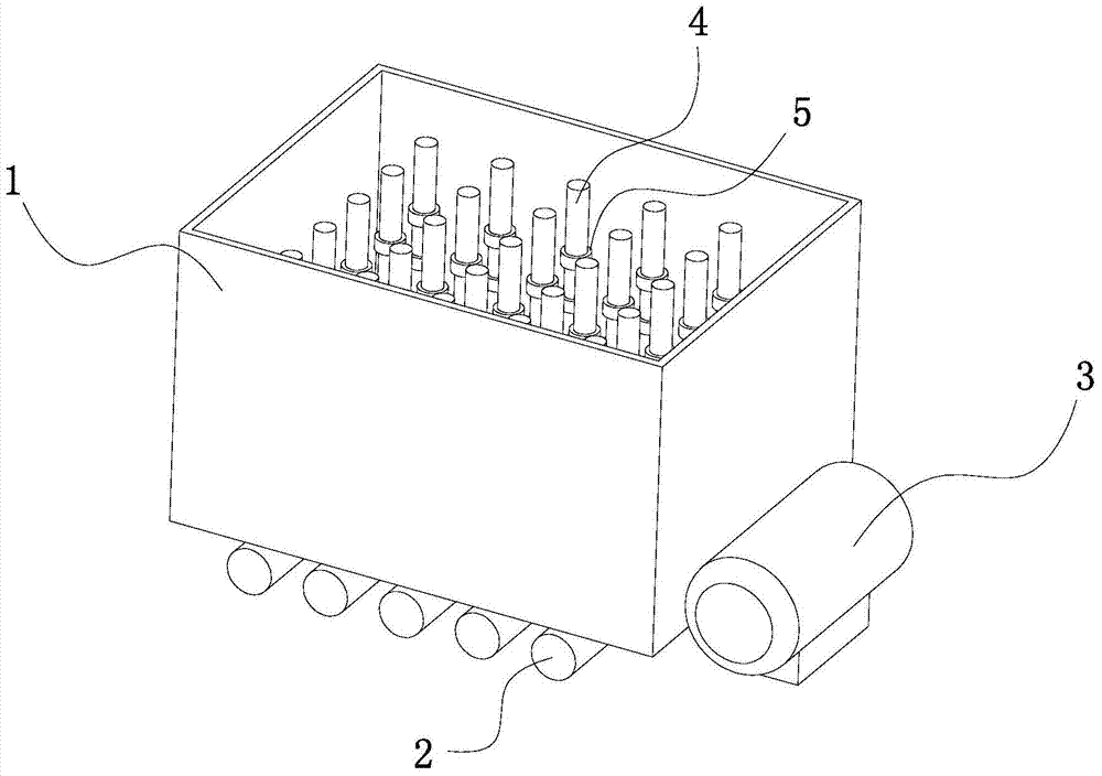
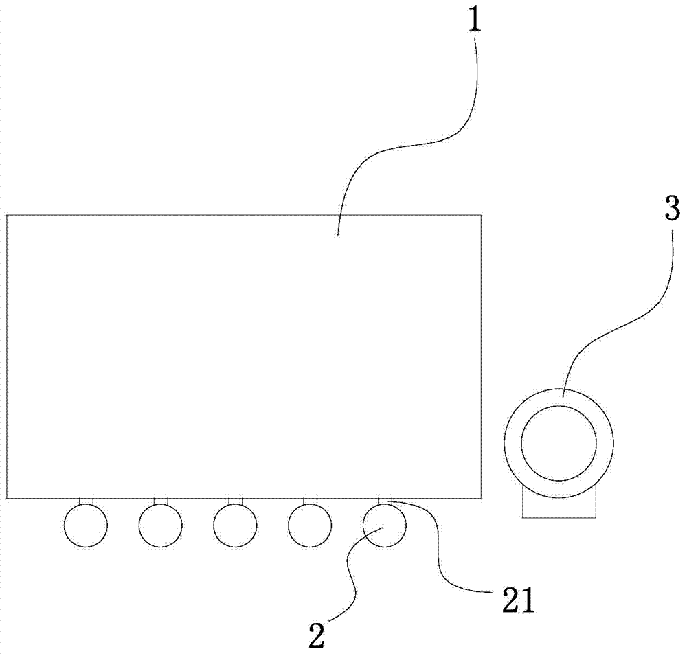
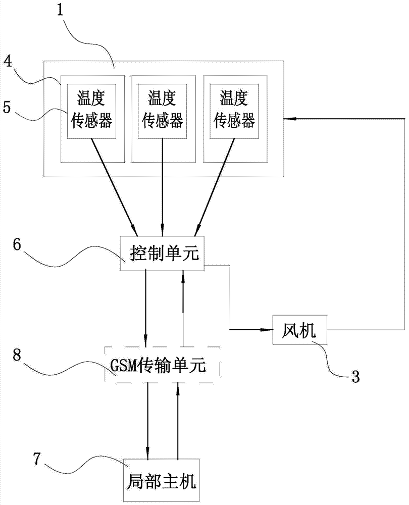
[0013] See figure 1 , figure 2 and image 3 , the present invention comprises a granary 1, the bottom of the granary 1 is equipped with a plurality of air ducts 2, the side walls of the air ducts 2 are respectively provided with a plurality of branch pipes 21 leading to the inside of the granary 1, and the air ducts 2 are connected with the fan 3 respectively; A plurality of evenly distributed monitoring rods 4 are inserted inside, and a plurality of temperature sensors 5 arranged up and down are arranged on the monitoring rod 4, and a temperature threshold value is set in the temperature sensor 5; the monitoring rods 4 are divided into multiple groups, and the monitoring rods 4 are arranged in a After grouping, the temperature sensor 5 on it is connected to the control unit 6 in groups, and the control unit 6 is connected to the local ...
PUM
 Abstract
Description
Claims
Application Information