Hand riveter

A technology of rivets and rivet heads, applied in the field of manual rivets, to achieve the effect of increasing mechanical advantages

Inactive Publication Date: 2014-07-16
CYCLONE TOOLS
View PDF2 Cites 4 Cited by
  • Summary
  • Abstract
  • Description
  • Claims
  • Application Information

AI Technical Summary

Problems solved by technology

While these drivers require significantly less force per stroke than the leverage-action rivets descri

Method used


Image

  • Hand riveter
  • Hand riveter
  • Hand riveter

Examples


Embodiment Construction

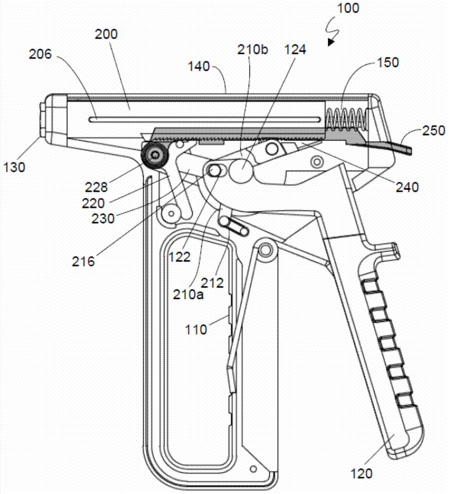
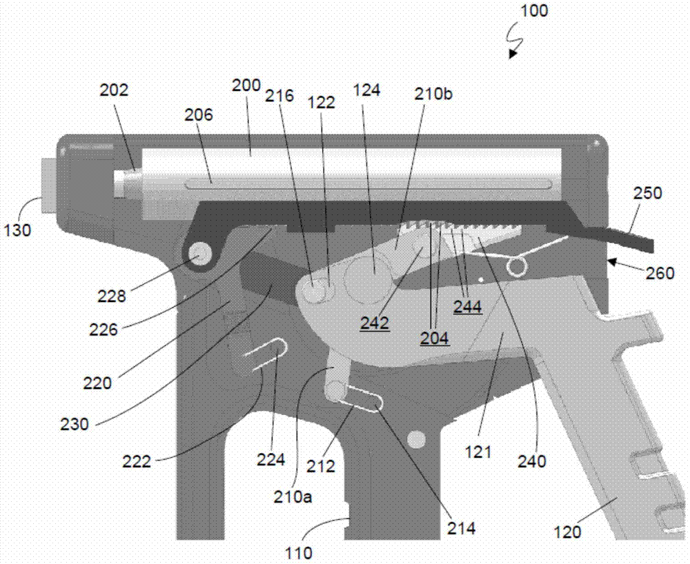
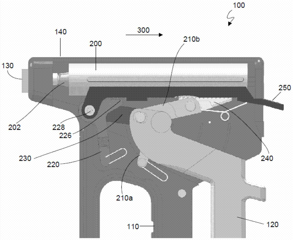
[0023] Referring to the drawings, hand riveter 100 includes a housing 140 having a mouth piece 130 for receiving a mandrel of a blind rivet. For simplicity, rivets are omitted from the drawings. The hand riveter 100 has a handle 110 and a handle 120 that can be squeezed to apply force to the mandrel. The handle 120 is mounted within the housing 140 and is capable of pivotal movement around a pivot point 124 ( figure 2 ).

[0024] The mandrel tensioning device mounted within the housing 140 includes a barrel 200 that houses a pair of jaws 202 that grip the mandrel. The jaws 202 are supported by compression springs within the barrel 200 . An inner cone located at the barrel opening allows the jaws to close the mandrel. Bucket 200 has elongated slots 206 that slide over tracks or other protrusions on the inner surface of housing 140 .

[0025] Helical teeth 204 located on the lower surface of bucket 200 and extending the main portion of its length are sized and shaped to ma...


PUM


Abstract

A hand riveter for setting a blind rivet having a rivet head, a rivet body and a mandrel extending through the rivet body, the hand riveter including: a housing having a mouthpiece for receiving the mandrel, a mandrel-tensioning means mounted within the housing, a drive means for applying a force to the mandrel-tensioning means to move the mandrel-tensioning means relative to the mouthpiece in a tensioning direction while the rivet head bears against the mouthpiece, thereby to increase tension in the mandrel, the drive means being engageable with a drive engagement component of the mandrel tensioning means; and a catch for preventing movement of the mandrel-tensioning means in a direction opposed to the tensioning direction; wherein the drive engagement component includes a plurality of teeth for ratcheting movement over the catch, and wherein the drive means includes a toggle linkage for increasing the force applied to the mandrel-tensioning means.

Description

technical field [0001] This invention relates to hand riveters. Background technique [0002] Blind rivets are often used as fasteners when the material to be secured can only be accessed through one side. Blind rivets consist of a tubular shank (the rivet body) with a rivet head at one end. A mandrel extends through the shank such that the mandrel head abuts the shank at the end opposite the rivet head. [0003] In use, the mandrel of the rivet is inserted into a hand riveter, electric riveter or pneumatic riveter, and the shank is inserted into the drilled hole from one side. With each stroke of the hand riveter, jaws attached to the pulling member of the riveter or riveter grip the mandrel and pull it through the shank so that the mandrel head deforms the shank. This process is repeated until the deformed end of the shank abuts the workpiece surface on the other side of the borehole, at which point the mandrel breaks (usually at a predetermined breaking point). If usi...

Claims


Application Information

Patent Timeline
IPC IPC(8): B21J15/38
CPCB21J15/386
Inventor 塔斯曼·J.·伍尔沃斯布莱恩·马歇尔
Owner CYCLONE TOOLS
Why Eureka
Try Eureka