Binary cylinder engine

a technology of cylinders and cylinder heads, applied in the direction of positive displacement engines, clutches, fluid couplings, etc., can solve the problems of reducing the efficiency of current designs, so as to achieve the effect of enhancing mechanical advantages

Active Publication Date: 2013-01-01
STAUSS RICHARD L
View PDF17 Cites 0 Cited by
  • Summary
  • Abstract
  • Description
  • Claims
  • Application Information

AI Technical Summary

Benefits of technology

[0007]A reciprocating engine of the invention is non-internal combustion pressure driven. The engine uses a lever system to achieve enhanced mechanical advantages in converting linear motion from pistons to rotary motion at a crankshaft. The engine includes a chassis, at least two sets of binary cylinders mounted on the chassis, and a crankshaft in operable association with the binary cylinders. Each cylinder in a binary cylinder set has a piston and a piston rod, wherein the piston rod is pivotally connected to a lever system. The lever system includes a piston lever, thrust rods and a central drive lever. The piston lever is pivotally attached to the chassis while the two thrust rods are pivotally attached to the piston lever and to the central drive lever. The central drive lever for each set of binary cylinders is rotatably mounted on a crankshaft throw. The lever system effectively transfers power to the crankshaft.

Problems solved by technology

Current designs are less than 20% efficient with over 60% of losses in wasted heat energy.
A non-internal combustion reciprocating engine as the sole source of powering a motor vehicle would be ideal, though given the power and speed demands of such vehicles may be difficult to achieve.

Method used


Image

  • Binary cylinder engine
  • Binary cylinder engine
  • Binary cylinder engine

Examples


Embodiment Construction

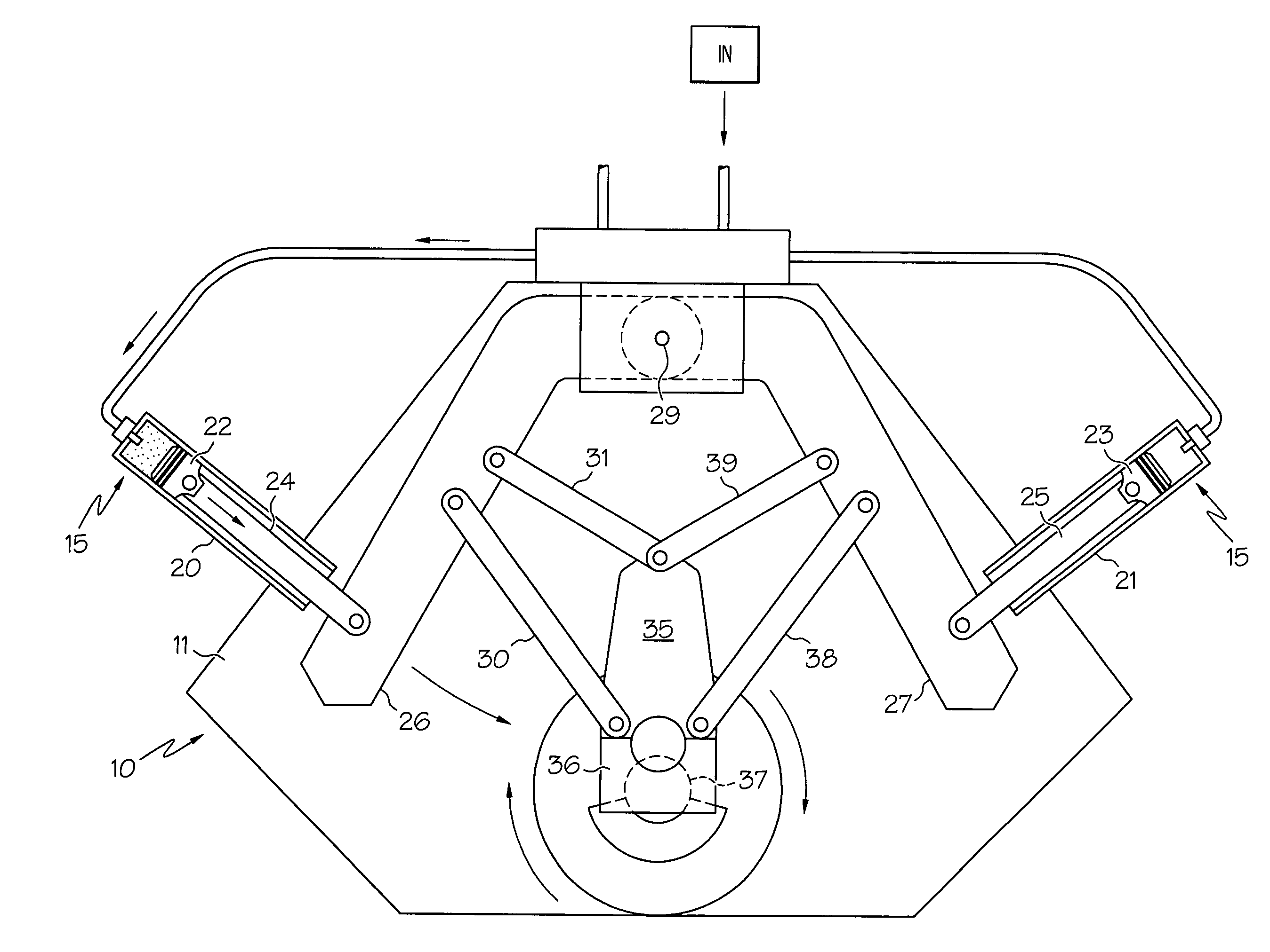
[0015]The engine of the invention comprises a chassis having at least two set of binary pistons linked to a crankshaft. The pistons are pressure driven e.g. by compressed air, heat expansion from a working fluid, or any other known means. The engine is a feasible alternative to conventional gasoline engines used in home and commercial applications. It can as well be used in the auto industry. For example, it can be used as the auto's sole source of power. Alternatively, the engine can be used in a hybrid auto to run the auto's generator while a gasoline engine supplies the main source of power.

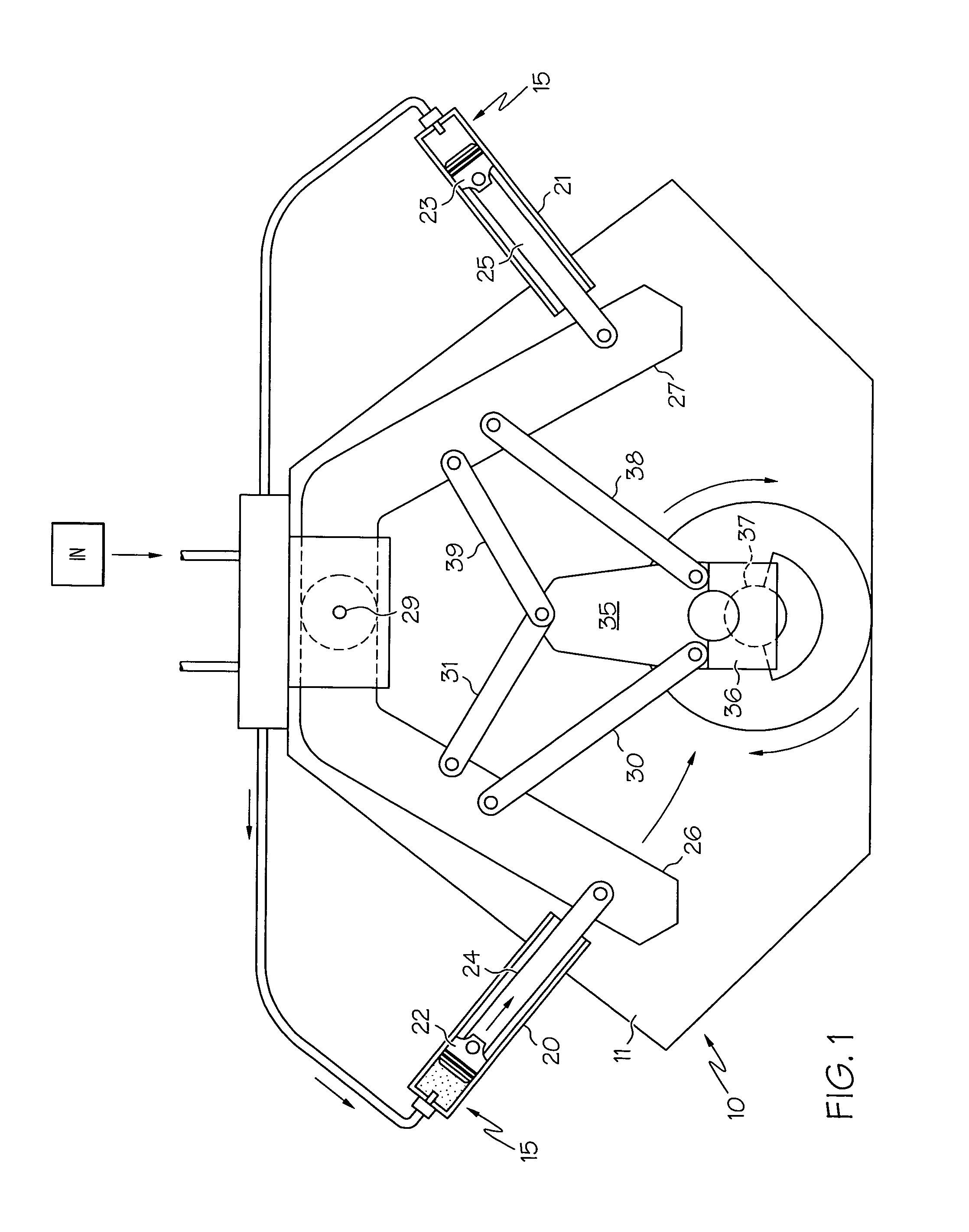
[0016]With reference to FIG. 1, there is shown the engine 10 of this invention mounted on a chassis 11. The chassis 11 is a frame for supporting the engine 10 and can take many forms. The chassis 11 can be a set of structural steel braces secured together in a configuration to support the engine's components. It can as well be an engine block with pistons mounted therein.

[0017]The essential co...


PUM


Abstract

A non-internal combustion reciprocating engine has an enhanced mechanical advantage lever system for efficiently converting linear motion from reciprocating pistons to rotary motion at a crankshaft. The engine comprises a chassis, at least two sets of binary cylinder systems mounted on the chassis, a crankshaft and a lever system. Each lever system has a piston lever, two thrust rods and a central drive lever. Each piston lever is pivotally attached to the chassis and pivotally attached to a piston rod extending from a piston cylinder. The two thrust rods are pivotally attached at one terminus to the piston lever and pivotally attached at a second terminus to the central drive lever. The two piston cylinders of each binary cylinder system work in concert to efficiently transfer power to the crankshaft.

Description

[0001]This application claims the benefit of U.S. Provisional Application No. 61 / 188,052, filed Aug. 7, 2008.FIELD OF THE INVENTION[0002]This invention relates to an energy efficient engine. More particularly, the invention relates to a non-internal combustion engine with sets of binary cylinder systems.BACKGROUND OF THE INVENTION[0003]Reciprocating engines, often called piston engines, are well known and extensively used throughout the world. The main types of reciprocating engines are the internal combustion engine, the steam engine and the Stirling engine. In all three types, one or more cylinders with a reciprocating piston inside produces a linear motion which is transferred to a crankshaft to produce a rotary motion. The rotary motion is then used for a work task by way of various gears, etc. The most prevalent of the engines is a four stroke cycle internal combustion engine used to power motor vehicles.[0004]While well known and commonly accepted, the common internal combusti...

Claims


Application Information

Patent Timeline
Patent Type & Authority Patents(United States)
IPC IPC(8): F01B1/00
CPCF01B9/02F01B1/04
Inventor STAUSS, RICHARD L.
Owner STAUSS RICHARD L
Why Eureka
Try Eureka