

Motorized Cylinder for Door Hardware
- Summary
- Abstract
- Description
- Claims
- Application Information
AI Technical Summary
Benefits of technology
Problems solved by technology
Method used
Image

Examples
Embodiment Construction
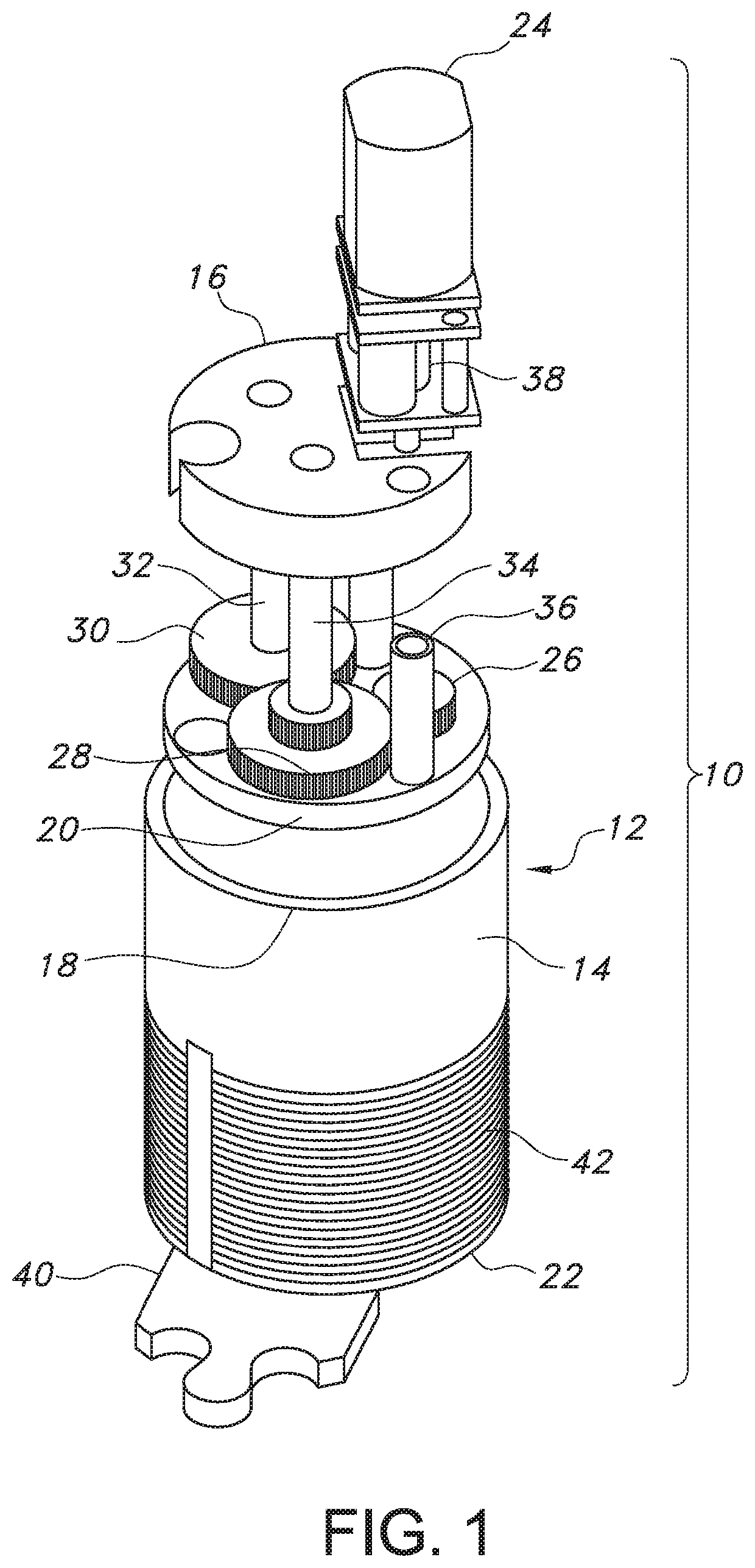
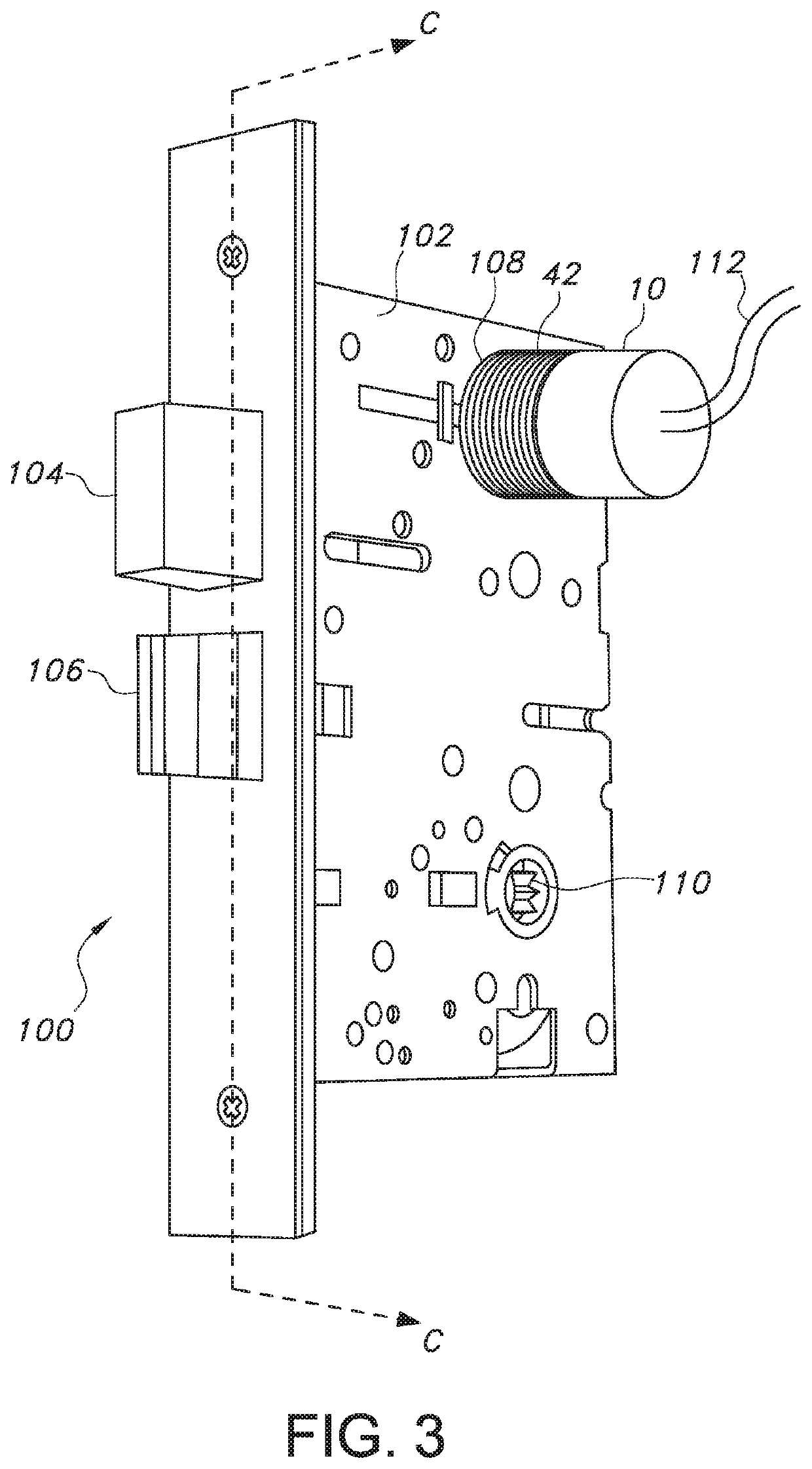
[0021]Referring now to the drawings, wherein like reference numerals designate corresponding structure throughout the views, FIG. 1 illustrates a motorized cylinder (10) according to one aspect of the present invention, which motorized cylinder (10) may be retrofit to replace a standard deadbolt cylinder of a door without requiring a complete redesign of the deadbolt.
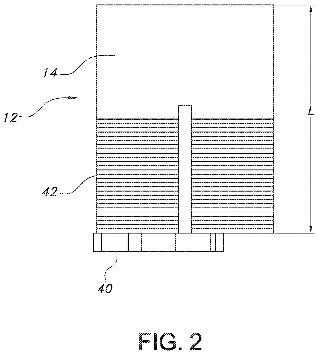
[0022]The motorized cylinder (10) includes a housing (12), defined by a generally cylindrical side wall (14) a generally planar outer end wall (16) disposed at a first end (18) of the side wall (14) and a generally planar inner end wall (20) disposed at a second end (22) of the side wall (14) opposite to the first end (18). As is discussed in more detail below, the housing (12) is configured for carrying and housing the various components of the motorized cylinder (10).
[0023]A relatively small gearmotor (24) is provided, which provides the power necessary to retract and / or throw the deadbolt. The gearmotor (24) is prefe...
PUM
 Abstract
Description
Claims
Application Information