Electric vehicle power battery pack temperature control system based on heat pipes

A technology for power battery packs and electric vehicles, applied in battery pack components, batteries, secondary batteries, etc., can solve the effect of battery pack temperature distribution uniformity, air short-circuit, the number of single cells, and thermal management effect limitations, etc. problem, to achieve the effect of obvious heating and cooling effect, good ability to protect the battery pack, and good thermal management effect

Active Publication Date: 2014-07-16
芜湖汇展新能源科技有限公司
View PDF7 Cites 27 Cited by
  • Summary
  • Abstract
  • Description
  • Claims
  • Application Information

AI Technical Summary

Problems solved by technology

[0004] Considering the factors of cost and manufacturing process, most of the thermal control media of power battery packs of electric vehicles is air at present, but because the air that needs to be heated or cooled needs to flow through each single battery, and there are often hundreds or even hundreds of them in the car. Thousands of single batteries, the gap between the single batteries is very small, even less than 1mm, which causes too much resistance to air circulation. Regulation, there are great restrictions on the number of single cells in the battery pack and the effect of thermal management
[0005] In the prior art, many thermal management schemes for battery packs place heating elements or cooling elements locally in the battery pack, which will inevitably result in the inability to perform the same degree of thermal management on all batteries inside the battery pack, thereby ensuring the uniformity of temperature distribution inside the battery pack. sex has a big impact
[0006] Publication number CN102139646A discloses a power battery thermal management system and its control method. The system adopts an open battery temperature control box, and the air-conditioning wind is brought into the battery pack by a fan to heat or cool the battery. When the flow resistance is large, this solution cannot guarantee the uniformity of the temperature field distribution inside the battery pack. At the same time, it is difficult for the open battery pack temperature control system to prevent water from entering the inside of the battery pack when the car is wading. certain security risks

Method used


Image

  • Electric vehicle power battery pack temperature control system based on heat pipes
  • Electric vehicle power battery pack temperature control system based on heat pipes
  • Electric vehicle power battery pack temperature control system based on heat pipes

Examples


Embodiment 1

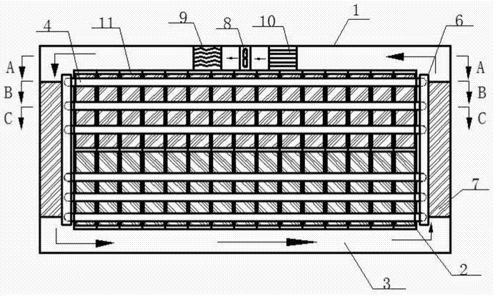
[0045] See figure, figure 2 , image 3 , Figure 4 with Figure 5 , the main cross-sectional view of the electric vehicle power battery pack temperature control system in this embodiment is as follows figure 1 As shown, the battery pack temperature control box 1 is an airtight box, which contains a closed battery group compartment 2 inside. The length and height of the battery pack compartment 2 are smaller than the battery pack box 1, but the width and temperature The width of the control box 1 is the same, and there is an annular heat exchange compartment 3 between the battery group compartment 2 and the battery pack temperature control box 1, and the annular heat exchange compartment 3 is formed on the top and bottom surfaces of the battery group compartment 2 , and along the two end faces of the battery group warehouse 2 in the length direction, there is a circulating heat transfer medium in the annular heat exchange warehouse 3 .

[0046] Such as figure 1 , figure 2...

Embodiment 2

[0055] see Image 6 In this embodiment, the heat transfer medium in the annular heat exchange chamber 3 is liquid, and the heater 10, the electromagnetic pump 13 and the evaporator 9 are arranged in series along the flow direction of the fluid. see Figure 7 In this embodiment, the back of the heat dissipation substrate 6 is arranged with staggered heat dissipation studs 14 . In this embodiment, 10×10 heat dissipation studs 14 are arranged in a staggered manner on the back of the heat dissipation substrate 6 .

[0056] The rest of the structure is the same as in Embodiment 1, and the working principle is consistent.

Embodiment 3

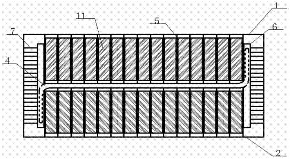
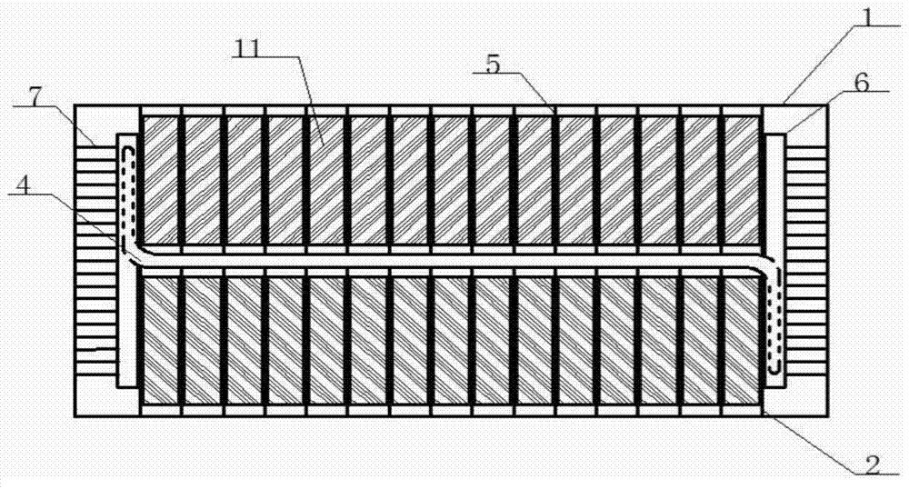
[0058] see Figure 8 with Figure 9 In this embodiment, a cylindrical single battery 11 is used, and the single battery 11 is installed horizontally between the insulating heat sinks 5 , and the insulating heat sink 5 is bonded to the two terminal surfaces of the single battery 11 . In this embodiment, 14 layers of single cells are arranged between two adjacent insulating fins 5 , each layer has 12 single cells 11 , and the distance between the single cells 11 is 2 mm.

[0059] The rest of the structural design is the same as in Embodiment 1, and the working principle is consistent.


PUM


Abstract

The invention discloses an electric vehicle power battery pack temperature control system based on heat pipes. The electric vehicle power battery pack temperature control system is characterized in that a battery pack temperature control box body is a sealed box body, a sealed battery grouping bin is contained in the sealed box body, the length and the height of the battery grouping bin are smaller than those of the battery pack temperature control box body, but the widths of the two components are equal; an annular heat exchange bin is formed between the battery grouping bin and the battery pack temperature control box body; the heat pipes are arranged in the battery grouping bin along the length direction in a penetration manner, the heat pipes penetrate through insulating heat sinks arranged in parallel, and the ends of the heat pipes are located in the annular heat exchange bin; single batteries are arranged between the insulating heat sinks, the radiating surfaces of the single batteries are fitted with the insulating heat sinks; a heater and an evaporator are respectively arranged in the annular heat exchange bin. The electric vehicle power battery pack temperature control system disclosed by the invention can be used for solving the problem that effective heat treatment cannot be performed on each single battery due to overlarge flow resistance and achieving sealed design of the battery box body, the safety is high, the temperature of the power battery is regulated quickly, and the temperature field distribution is uniform.

Description

technical field [0001] The invention relates to the technical field of thermal management of power batteries of new energy vehicles in the world, in particular to a temperature control system for power battery packs of electric vehicles based on heat pipes. Background technique [0002] The technical key of electric vehicles is the power battery. The performance of the power battery directly determines the performance, safety and service life of the electric vehicle. Since the temperature will directly affect the safety performance and life of the battery, if the temperature is too low, the performance of the vehicle will be reduced, and if it is too high, it may cause a safety accident. At the same time, the space on the vehicle is limited, and the batteries are closely connected and loaded in the car battery pack. The power battery will release a lot of heat during the charging and discharging process and when it is used in a high-temperature environment, and the heat will...

Claims


Application Information

Patent Timeline
Patent Type & Authority Applications(China)
IPC IPC(8): H01M10/617H01M10/625H01M10/6552H01M2/02H01M10/655H01M50/244H01M50/249
CPCH01M2220/20H01M50/20Y02E60/10
Inventor 唐志国江超郝嘉欣李荟卿张丹阳王元哲钱立军
Owner 芜湖汇展新能源科技有限公司
Why Eureka
Try Eureka