Permanent-magnet biased hybrid magnetic bearing switch reluctance motor

A technology of switched reluctance motors and hybrid magnetic bearings, applied in the direction of magnetic attraction or thrust holding devices, electrical components, electromechanical devices, etc., can solve the problems of increasing winding inductance, low power density of motors, and low power density. Achieve the effect of improving radial bearing capacity, good high-speed suspension performance, and large radial suspension force

Active Publication Date: 2014-09-10
NANJING UNIV OF POSTS & TELECOMM
View PDF4 Cites 15 Cited by
  • Summary
  • Abstract
  • Description
  • Claims
  • Application Information

AI Technical Summary

Problems solved by technology

[0004] The bearingless switched reluctance motor is a very complex and highly nonlinear system, there is a strong coupling between the torque and the suspension force, and it is difficult to realize the complete decoupling of the two in the control strategy and mathematical model, which is One of the main factors that make it difficult to improve the suspension and running performance of the bearingless switched reluctance motor
In addition, due to the need for suspension force control, the winding current must be controlled by chopping. When running at high speed, the dual effects of motion electromotive force and induced electromotive force make it impossible to perform tracking and chopping control on the current, that is, there will be a phenomenon that the chopping cannot be performed. This greatly affects the high-speed performance of the bearingless switched reluctance motor
[0005] In order to solve the above two shortcomings of the bearingless switched reluctance motor, scholars at home and abroad have done a lot of work, and proposed a mixed stator tooth single winding bearingless switched reluctance motor with 8 / 10 and 12 / 14 structures by changing the stator structure. It is characterized in that the suspension force and torque are separately generated by the suspension winding and the torque winding, the motor is a two-phase working system, and the power density of the motor is low; by changing the connection mode of the suspension winding, a series-excited double-winding bearingless switching magnetic switch is proposed. Resistance motor, which connects the three-phase levitation windings in the same direction in series into a set of windings, so that the magnetic permeability of the levitation winding remains constant in one rotor cycle, and the levitation current does not generate torque, which realizes the structural solution of torque and levitation force coupling, but the enameled wire of the suspension winding has a large demand, consumes copper, and the winding utilization is low; by increasing the rotor pole arc and changing the combination of the stator and rotor poles, the bearingless structure of 12 / 4, 12 / 8 and 16 / 4 poles is proposed Switched reluctance motor, however, the increase of the rotor pole arc compresses the torque output width, and the power density is low; by adding a radial magnetic bearing in the axial direction, a composite structure single-winding bearingless switched reluctance motor is proposed, the magnetic The increase of the bearing part increases the inductance of the winding, resulting in an increase in the rise and fall time of the winding current, which is not conducive to the suspension control during high-speed operation, thereby reducing the suspension accuracy

Method used


Image

  • Permanent-magnet biased hybrid magnetic bearing switch reluctance motor
  • Permanent-magnet biased hybrid magnetic bearing switch reluctance motor
  • Permanent-magnet biased hybrid magnetic bearing switch reluctance motor

Examples


Embodiment Construction

[0029] The technical scheme of a permanent magnet bias hybrid magnetic bearing switched reluctance motor of the present invention will be described in detail below in conjunction with the accompanying drawings:

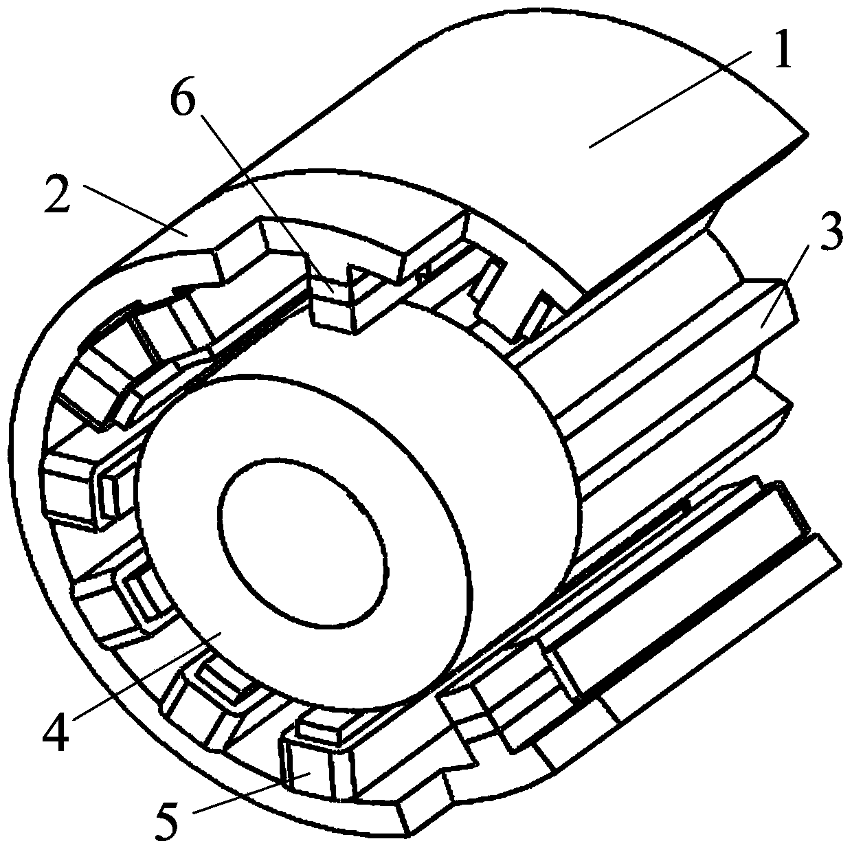
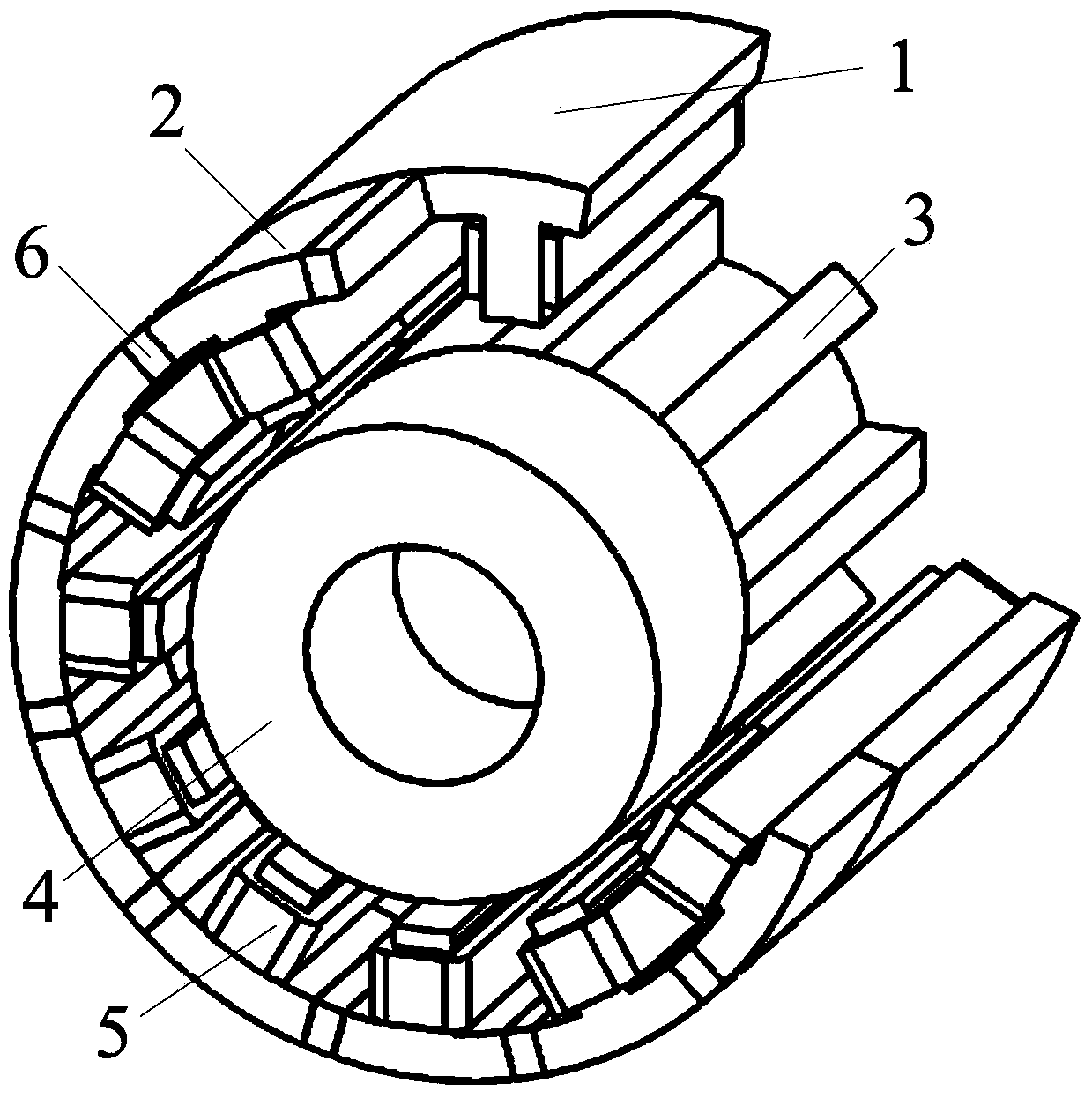
[0030] Such as figure 1 As shown, a three-dimensional structure schematic diagram of a permanent magnet bias hybrid magnetic bearing switched reluctance motor embodiment 1 of the present invention, wherein, 1 is the torque stator, 2 is the suspension force stator, 3 is the torque rotor, 4 is Levitation force rotor, 5 is winding, 6 is permanent magnet;

[0031] The stator of the motor is composed of a torque stator and a levitation force stator through axial superposition. The torque stator and the levitation force stator are both salient pole structures, and the number of teeth is 12. The torque stator and the levitation force stator are located between teeth and teeth alignment state;

[0032] The motor rotor is composed of a torque rotor and a levitation force rot...


PUM


Abstract

The invention provides a permanent-magnet biased hybrid magnetic bearing switch reluctance motor. A torque stator and a suspension force stator of the motor are axially superposed, and a torque rotor and a suspension force rotor of the motor are axially superposed; each of the torque stator and the suspension force stator both is of a salient pole structure and provided with twelve teeth; the torque rotor is of the salient pole structure and provided with eight teeth, while the suspension force rotor is of a cylindrical structure; windings, twelve in total, are wound around a stator tooth formed by the torque stator and the suspension force stator; an annularly magnetized permanent magnet is placed on each of twelve stator yokes, or a radially magnetized permanent magnet is placed on each of twelve suspension force stator teeth. The motor is characterized in that decoupling of torque and suspension force is realized structurally and convenient control is achieved, permanent magnets are used for providing biased magnetic flux and large radial bearing capacity is realized, and the influence of motional electromotive force on current chopping control is eliminated, and good current control effect and good high speed adaptability are achieved.

Description

technical field [0001] The invention belongs to the technical field of motors, and relates to a permanent magnet bias hybrid magnetic bearing switched reluctance motor. Background technique [0002] The bearingless switched reluctance motor is a new type of magnetic levitation motor developed at the end of the 20th century. The double-winding bearingless switched reluctance motor is to stack the levitation winding that generates the levitation force and the winding of the original switched reluctance motor on the stator of the motor. By controlling the current of the two sets of windings, it has the ability to rotate and self-levitate simultaneously, so that Achieve ultra-high-speed operation of the motor. The single-winding bearingless switched reluctance motor has the ability to rotate and self-suspend at the same time by controlling the current of a set of windings. [0003] The main disadvantage of the double-winding bearingless switched reluctance motor is an extra se...

Claims


Application Information

Patent Timeline
Patent Type & Authority Applications(China)
IPC IPC(8): H02K16/00H02N15/00H02K3/28
Inventor 刘泽远杨艳曹鑫邓智泉王世山
Owner NANJING UNIV OF POSTS & TELECOMM
Why Eureka
Try Eureka