Quench mixer used for hydrogenation reactor

A technology for hydrogenation reactors and mixers, which is applied in the direction of fluid mixers, mixers, chemical instruments and methods, etc. It can solve the problems of high flow resistance of mixture flow and poor mixing effect, and achieve enhanced swirl mixing effect Effect

Active Publication Date: 2014-10-15
LUOYANG PETROCHEMICAL ENG CORP SINOPEC +1
View PDF3 Cites 6 Cited by
  • Summary
  • Abstract
  • Description
  • Claims
  • Application Information

AI Technical Summary

Problems solved by technology

[0004] The purpose of this invention is to provide a kind of quenching mixer for hydrogenation reactor, to solve the existing mixing effect when the existing quenching mixer is used for mixing and distributing more mixture flow of gaseous reactants, mixing The problem of large flow resistance of logistics

Method used


Image

  • Quench mixer used for hydrogenation reactor
  • Quench mixer used for hydrogenation reactor
  • Quench mixer used for hydrogenation reactor

Examples


Embodiment Construction

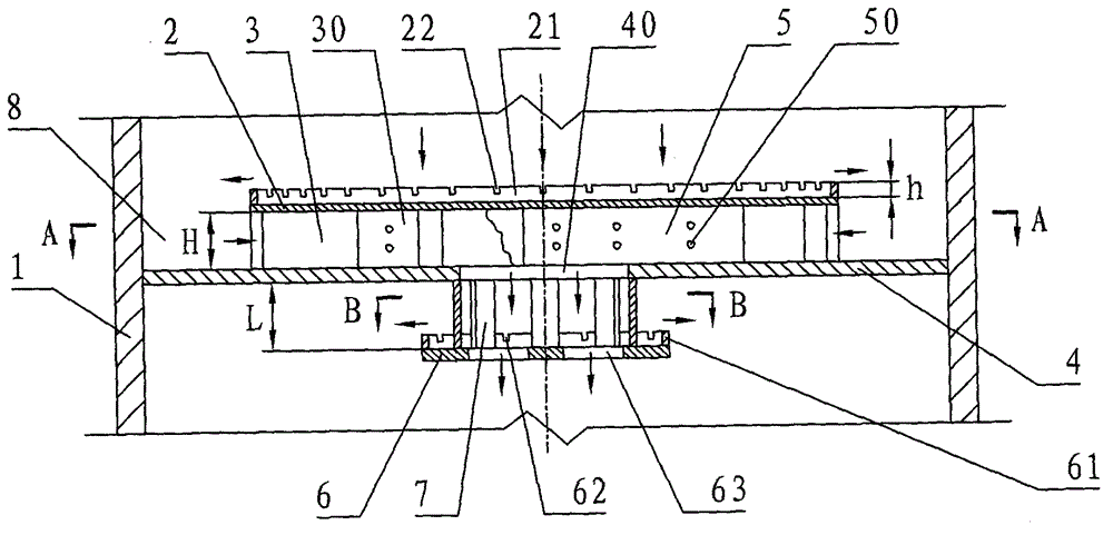
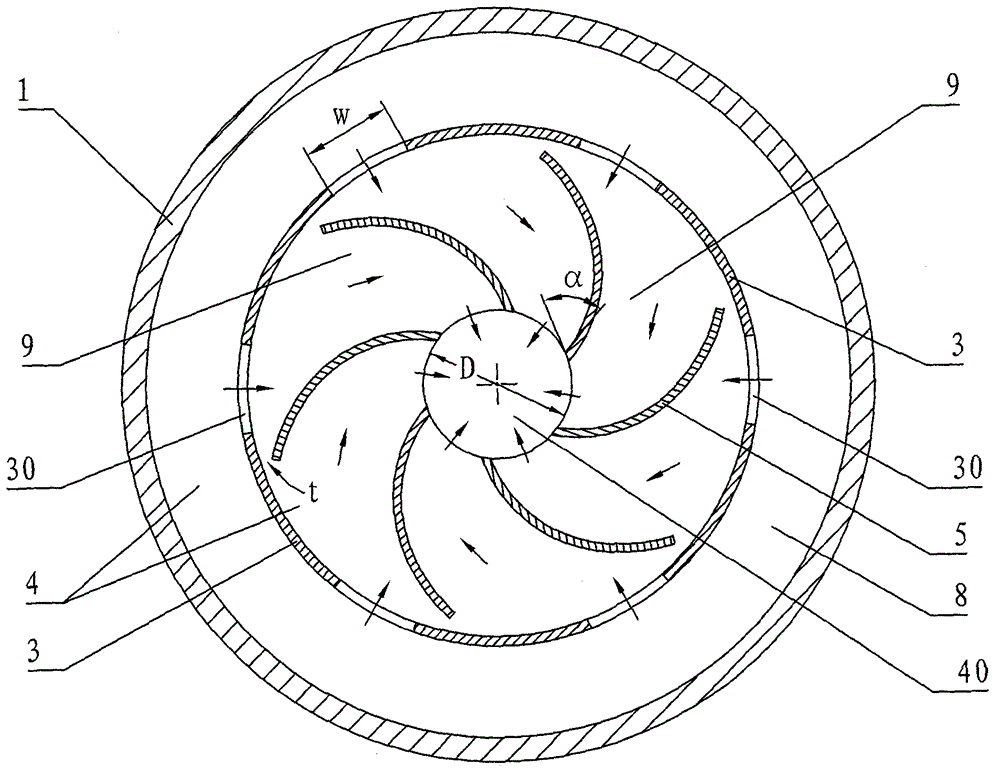
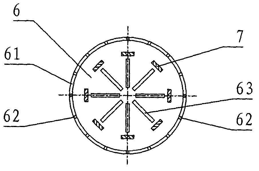
[0013] see figure 1 , figure 2 , the present invention is used in the quench mixer of the hydrogenation reactor (abbreviated as the quench mixer or mixer), provided with the swirl plate 5 . The top of the swirl plate 5 is connected with the top baffle plate 2 , and the bottom of the swirl plate 5 is connected with the interceptor plate 4 . A central hole 40 is provided at the center of the cutoff plate 4 , a distribution plate 6 is provided below the central hole 40 , and a distribution plate slit 63 is provided on the distribution plate 6 . The distribution plate 6 is fixed on the cut-off plate 4 through the connecting rib 7 . Between the top baffle 2 and the cut-off plate 4, at least four circular arc plates 3 are uniformly arranged around the edge of the top baffle 2 and at the outer end of the swirl plate 5, and a circular arc plate 3 is formed between two adjacent circular arc plates 3. The mixture flows into port 30 . The top baffle 2 and the cutoff plate 4 are conn...


PUM


Abstract

The invention discloses a quench mixer used for a hydrogenation reactor and aims to solve problems that a mixing effect is poor and a flow resistance of a mixed material flow is large when a quench mixer in the prior art is used for mixing and distributing a mixed material flow having a large amount of gas-phase reactants. The quench mixer is provided with a plurality of rotational-flow plates (5), wherein tops of the rotational-flow plates (5) are connected to a top baffle (2) and bottoms of the rotational-flow plates (5) are connected to a shutoff plate (4). A central hole (40) is formed in the center of the shutoff plate (4). A distribution plate (6) is arranged under the central hole. At least four arc-shaped plates (3) are disposed between the top baffle and the shutoff plate, around an edge of the top baffle and at external ends of the rotational-flow plates. A mixed material flow inlet (30) is arranged between each two adjacent arc-shaped plates. Each rotational-flow plate is arranged at a position corresponding to each mixed material flow inlet. A top baffle folded-edge (21) is disposed at the periphery of the top baffle. A distribution plate folded-edge (61) is disposed at the periphery of the distribution baffle. The quench mixer is mainly used in the hydrogenation reactor used for processing light-weight oil.

Description

technical field [0001] The invention relates to a quenching mixer used for a hydrogenation reactor in petroleum refining and petrochemical industry, which belongs to the internal component of the hydrogenation reactor. Background technique [0002] In petroleum refining and petrochemical industry, hydrogenation reaction is very common and widely used, such as hydrocracking and hydrofining. The hydrogenation reaction is an exothermic reaction, and the temperature of the reactants needs to be controlled during the reaction to prevent the catalyst bed temperature from rising rapidly and causing the activity of the catalyst to decrease. In industrial design, the catalyst in the fixed-bed hydrogenation reactor is usually divided into multiple beds, and cold hydrogen is added between two adjacent beds. hydrogen. The quench mixer is a place for mixing hot reactants and cold hydrogen and exchanging heat, and is an important internal component of the hydrogenation reactor. Quenchi...

Claims


Application Information

Patent Timeline
Patent Type & Authority Applications(China)
IPC IPC(8): B01J8/08B01F5/06
Inventor 陈强蔡连波赵晓青盛维武庞晶晶
Owner LUOYANG PETROCHEMICAL ENG CORP SINOPEC
Why Eureka
Try Eureka