Stroboflash-free high-precision constant-current LED (light emitting diode) drive circuit and operating method thereof

A technology of LED driver and LED driver, applied in the direction of electric lamp circuit arrangement, electric light source, lighting device, etc., can solve problems such as increasing production cost, achieve the effect of good reliability, avoid LED stroboscopic problem, and simplify peripheral circuit

Inactive Publication Date: 2014-12-10
山东申鑫电子有限公司
View PDF6 Cites 1 Cited by
  • Summary
  • Abstract
  • Description
  • Claims
  • Application Information

AI Technical Summary

Problems solved by technology

At present, if high PFC is required, two stages must be considered. The front stage uses unipolar PFC to make a constant voltage, and the latter stage converts the voltage into a constant current. This design greatly increases the production cost.

Method used


Image

  • Stroboflash-free high-precision constant-current LED (light emitting diode) drive circuit and operating method thereof
  • Stroboflash-free high-precision constant-current LED (light emitting diode) drive circuit and operating method thereof
  • Stroboflash-free high-precision constant-current LED (light emitting diode) drive circuit and operating method thereof

Examples


Embodiment 1

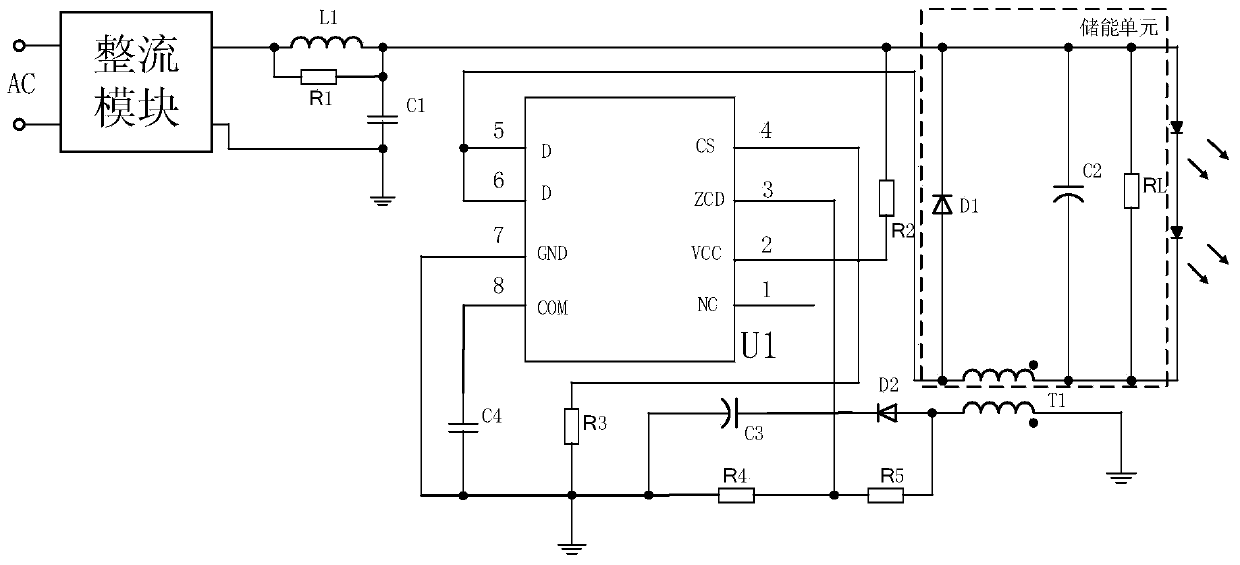
[0025] figure 1 A circuit diagram of the high constant current precision LED drive circuit is shown.

[0026] Such as figure 1 As shown, a flicker-free high constant current precision LED drive circuit, including:

[0027] An LED driver U1 containing a MOS tube and a feedback signal input terminal, and an energy storage unit connected to the LED driver U1; the energy storage unit is coupled with a feedback loop through mutual inductance to obtain a feedback signal, and the feedback signal is input through a feedback branch To the feedback signal input terminal ZCD.

[0028] Specifically, the pins of the LED driver U1: 1-pin NC terminal (floating), 2-pin VCC terminal (power supply), 3-pin feedback signal input terminal, 4-pin CS terminal (source of MOS tube), 5-pin and 6 pins (MOS transistor drain), 7 pins are grounded, and 8 pins are loop compensation pins.

[0029] The energy storage unit includes: a freewheeling tube D1, a capacitor C2, an output resistor RL, and a prima...

Embodiment 2

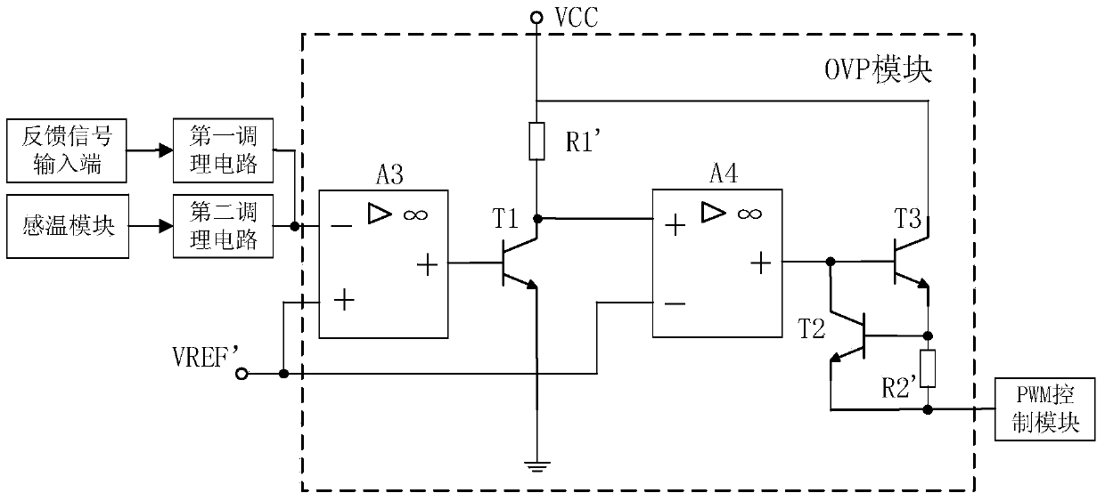
[0043] The working method of the high constant current precision LED drive circuit based on Embodiment 1, the working method includes: an overvoltage protection method, the method includes:

[0044] The OVP module judges whether to output an overvoltage protection signal according to the obtained feedback signal; if the feedback signal is greater than the overvoltage protection reference voltage, then output the overvoltage protection signal, and the PWM control module outputs the overvoltage protection signal according to the overvoltage protection signal The LED driver is locked out.

[0045] In this embodiment, the specific implementation of the OVP module is the same as that in Embodiment 1, and will not be repeated here.

[0046] Further, the working method also includes: a method for overheating protection, which includes:

[0047] The temperature signal is converted into a voltage signal by a temperature sensing module and then input to the OVP module through the secon...


PUM


Abstract

The invention relates to a stroboflash-free high-precision constant-current LED (light emitting diode) drive circuit and an operating method thereof. The high-precision constant-current LED drive circuit comprises an LED drive and an energy storage unit connected with the LED drive, the LED drive is internally provided with an MOS (metal oxide semiconductor) tube and a feedback signal input end, and the energy storage unit is coupled with a feedback circuit to acquire feedback signals which are inputted into the feedback signal input end. The stroboflash-free high-precision constant-current LED drive circuit has the advantages that by the aid of the LED drive internally provided with the MOS tube and the feedback signal input end, integrity of the drive circuit is improved, and the problem of LED stroboflash can be avoided only by one LED drive; a peripheral circuit of the LED drive circuit is more simplified by an internal overvoltage protector, and high reliability is achieved; the LED drive is free of hiccups and is directly locked when an output voltage is higher than an overvoltage protection reference voltage, so that the LED drive is further protected.

Description

technical field [0001] The invention relates to an LED drive circuit, in particular to a flicker-free high constant current precision LED drive circuit and its working method. Background technique [0002] In the field of lighting, there have been relevant biological and medical studies on the damage caused by stroboscopic flash to the human body. First, it may cause brain cell damage. Second, it may affect reading and vision. Third, it may reduce work efficiency and cause work-related injuries. In order to overcome the above defects, LED lighting can be used. [0003] Although LED lighting fixtures use a constant DC power supply, it is theoretically possible to achieve constant lighting without flicker. But in fact, considering the cost of LED drive circuits, most manufacturers use unipolar PFC circuits. Therefore, the current output to the LED is not a straight line. Therefore, there will still be varying degrees of LED strobe. [0004] For LED applications, the unipol...

Claims


Application Information

Patent Timeline
Patent Type & Authority Applications(China)
IPC IPC(8): H05B37/02
Inventor 张永良
Owner 山东申鑫电子有限公司
Why Eureka
Try Eureka