Multilevel microcirculation condition monitoring device and method

A state monitoring device and multi-level technology, applied in diagnostic recording/measurement, medical science, sensors, etc., can solve problems such as single field of view and numerical aperture, inability to observe carefully, and inability to clearly image the state of multi-level microcirculation, etc., to achieve Simple operation effect

Active Publication Date: 2014-12-24
GUANGZHOU MEDSOFT SYST LTD
View PDF12 Cites 9 Cited by
  • Summary
  • Abstract
  • Description
  • Claims
  • Application Information

AI Technical Summary

Problems solved by technology

[0003] The current microcirculation imaging device based on orthogonal polarization imaging has limitations, which are mainly reflected in: On the one hand, polarized light of a single wavelength is used to project the skin surface, so that the polarized light can only be transmitted to a specific depth or can only be observed to the microvessels at a specific depth, and the microcirculation is distributed in a three-dimensional form; on the other hand, a single adjustment of the field of view and numerical aperture of the microcirculation imaging device can only improve the field of view and image resolution of microvessels at a specific depth, However, it is impossible to carefully observe the multi-level microcirculation state areas distributed in three-dimensional form; in addition, for patients in shock, due to the insufficient microcirculation perfusion in various organs and tissues, the perfusion of each microcirculation area can be observed in real time. The state has important clinical significance. It is difficult or impossible for ordinary microcirculation imaging devices to judge the depth of the obtained microcirculation imaging information of shock patients, and it is also unable to clearly image the multi-level microcirculation states at different depths.

Method used


Image

  • Multilevel microcirculation condition monitoring device and method
  • Multilevel microcirculation condition monitoring device and method
  • Multilevel microcirculation condition monitoring device and method

Examples


Embodiment Construction

[0036] The following will clearly and completely describe the technical solutions in the embodiments of the present invention with reference to the drawings in the embodiments of the present invention.

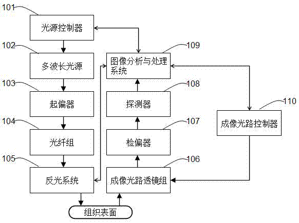
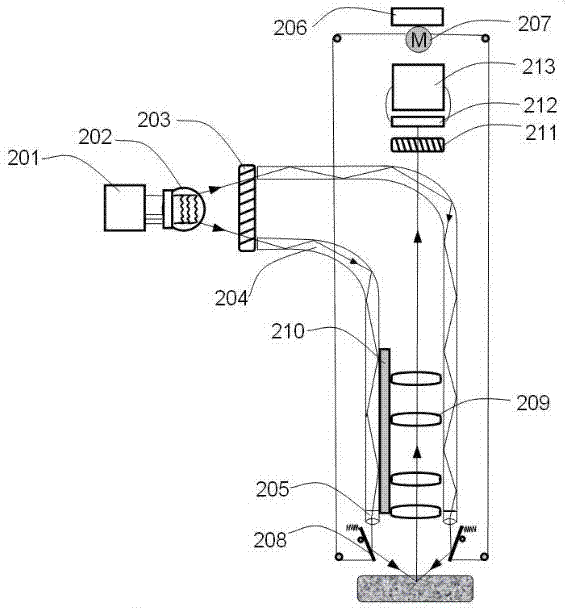
[0037] see figure 1 , is a structural block diagram of an embodiment of the multi-level microcirculation state monitoring device provided by the present invention.

[0038] In this embodiment, the multi-level microcirculation state monitoring device includes: a light source controller 101, a multi-wavelength light source 102, a polarizer 103, an optical fiber group 104, a reflection system 105, an imaging optical path lens group 106, and a polarizer 107 , a detector 108 , an image analysis and processing system 109 and an imaging optical path controller 110 .

[0039]The basic working principle of the multi-level microcirculation state monitoring device is: according to the target depth level of the microcirculation in the human tissue to be monitored, the imaging optical pat...


PUM


Abstract

The invention discloses a multilevel microcirculation condition monitoring device which comprises a light source controller, a multi-wave-length light source, a polarizer, an optical fiber group, a light reflecting system, an imaging light path lens group, an analyzer, a detector, an image analyzing and processing system and an imaging light path controller. The imaging light path controller controls the imaging focusing distance of the imaging light path lens group. The light source controller drives the multi-wave-length light source to emit lighting light beams with different wave lengths and powers. The light reflecting system controls polarization lighting light beams to be projected to the incident angle of the surface of tissue. According to the device, by changing the four parameters of the imaging focusing distance, the lighting light beam wave length and power and the incident angle of the polarization lighting light beams projected to the surface of the tissue, the image analyzing and processing system can capture the multilevel microcirculation condition information in different depths in the human body tissue clearly in real time. The invention further discloses a multilevel microcirculation condition monitoring method.

Description

technical field [0001] The invention relates to the technical field of biological optical imaging, in particular to a multi-level microcirculation state monitoring device and method capable of monitoring different depths in human tissues. Background technique [0002] In the human blood circulation system, microcirculation refers to the blood circulation between arterioles and venules. The most fundamental function of blood circulation is to exchange substances between blood and tissues. This function is realized in the microcirculation part. Every organ and every tissue cell of the human body must be supplied with oxygen and nutrients by the microcirculation, transfer energy, and remove carbon dioxide and metabolic waste. Once the microcirculation of the human body is disturbed, the corresponding tissue system or internal organs will be affected and cannot perform normal functions, which will easily lead to the failure of human organs, the disorder of immune function and th...

Claims


Application Information

Patent Timeline
Patent Type & Authority Applications(China)
IPC IPC(8): A61B5/00
Inventor 刘发杰郑鹏飞亚历克斯·布兰多罗晓川
Owner GUANGZHOU MEDSOFT SYST LTD
Why Eureka
Try Eureka