Umbrella-shaped antenna reflector

An umbrella antenna and reflector technology, which is applied in the field of large-diameter and high-precision umbrella antenna reflectors, can solve the problem that it does not have high profile accuracy and profile retention capability, and the profile accuracy of the antenna reflector is difficult to meet the requirements. The loss of the effective reflection area of ​​the antenna reflector can achieve the effect of simple and feasible structure, high profile accuracy and profile retention capability, and improved stiffness.

Active Publication Date: 2015-01-07
SHANGHAI YS INFORMATION TECH
View PDF5 Cites 30 Cited by
  • Summary
  • Abstract
  • Description
  • Claims
  • Application Information

AI Technical Summary

Problems solved by technology

[0005] 1. The umbrella-shaped antenna reflector cannot be unfolded smoothly at all. Even if the reflector can be barely unfolded, the surface accuracy of the antenna reflector after unfolding is difficult to meet the requirements
[0006] 2. When the diameter of the antenna reflector is further increased, the deployment power required by the antenna reflector is further increased, which makes the deployment mechanism become extremely large, and the weight of the antenna reflector increases sharply. At the same time, the effective reflection area of ​​the antenna reflector increases. Large losses, seriously affecting the performance of the antenna reflector
[0007] 3. In the harsh high and low temperature environment in space, the profile of the antenna reflector is prone to change, the stability of the profile system is not high, and it does not have high profile accuracy and profile retention ability
[0008] 4. The expansion rib has a large weight and low rigidity, especially the root of the expansion rib is prone to deformation, which will affect the stability of the antenna reflector and affect the performance of the antenna reflector

Method used


Image

  • Umbrella-shaped antenna reflector
  • Umbrella-shaped antenna reflector
  • Umbrella-shaped antenna reflector

Examples


Embodiment Construction

[0045] The advantages of the present invention will be further elaborated below in conjunction with specific embodiments and accompanying drawings.

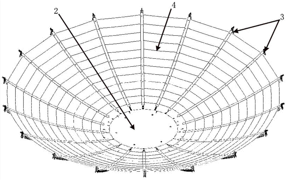
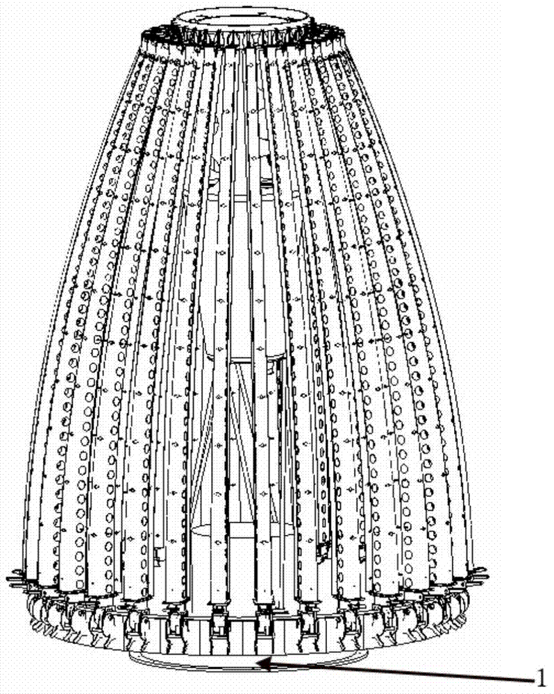
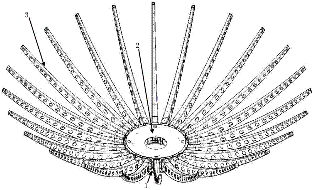
[0046] Such as Figure 1 to Figure 7 As shown in , the umbrella-shaped antenna reflector of the present invention includes a base 1, a fixed surface part 2, an expandable part, a mesh surface part 4 and a driving assembly. Such as image 3 and Figure 4As shown, the base 1 is a cavity structure, one side of the base 1 is fixed on the antenna support (not shown), the other side is fixed to the fixed surface part 2, and the edge of the base is between the two sides. The base edge is preferably a cylindrical edge or a polygonal edge. The solid surface part 2 is a solid surface reflector. The expandable part includes a plurality of expansion ribs 3, and the number of expansion ribs 3 can be specifically set according to actual conditions. The expansion rib 3 includes a top and a root, and the cross section of the root is greater...


PUM


Abstract

The invention provides an umbrella-shaped antenna reflector which comprises a base, a fixing face part, a foldable part, a mesh face part and a driving assembly. The fixing face part is a fixing face reflector body. The foldable part comprises a plurality of unfolding ribs. The mesh face part comprises a front tension mesh and a rear tension mesh. The driving assembly comprises a motor and a power rope. The fixing face part is fixedly connected with the base. The foldable part is connected with the base in a hinged mode. The mesh face is arranged on the foldable part. The umbrella-shaped antenna reflector can be unfolded smoothly through the driving assembly. The umbrella-shaped antenna reflector is provided with a large diameter and high in accuracy, has the advantages of being high in molded surface accuracy, high in molded surface keeping capacity, high in stability and high in reflection efficiency and can be applied to the outer space, and the unfolding ribs are large in rigidity.

Description

technical field [0001] The invention relates to an antenna reflector, in particular to a large-caliber high-precision umbrella-shaped antenna reflector applied in space. Background technique [0002] Umbrella-shaped antenna reflectors used in space are similar in structure to umbrellas, mainly composed of spreading ribs and metal reflective nets. The expansion ribs are connected to the base of the umbrella-shaped antenna reflector through hinges, and the metal reflection net is laid on the expansion ribs. The antenna reflector is first folded into a column shape. After the antenna reflector reaches the predetermined position in space, the expansion ribs are driven by the expansion mechanism at the bottom of the antenna reflector to expand. After the antenna reflector is deployed in place, it is like a stretched umbrella. [0003] Among the existing umbrella antenna reflectors, according to the mesh structure and deployment method, they can be mainly divided into: single-la...

Claims


Application Information

Patent Timeline
Patent Type & Authority Applications(China)
IPC IPC(8): H01Q15/16
Inventor 马小飞侯仰青王晓凯
Owner SHANGHAI YS INFORMATION TECH
Why Eureka
Try Eureka