Correction method for radar receiving channel array

A technology of receiving channel and correction method, which is applied in the direction of radio wave measurement system, instrument, etc., can solve problems such as unsatisfactory correction effect, achieve stable and reliable correction effect, and overcome the effect of gain inconsistency

Active Publication Date: 2015-01-21
CNGC INST NO 206 OF CHINA ARMS IND GRP
View PDF5 Cites 12 Cited by
  • Summary
  • Abstract
  • Description
  • Claims
  • Application Information

AI Technical Summary

Problems solved by technology

The basic principle of the far-field signal method is very simple, but in practical applications, it is easily affected by the shape of the signal source horn pattern, the shape of the unit pattern of the rec...

Method used


Image

  • Correction method for radar receiving channel array
  • Correction method for radar receiving channel array
  • Correction method for radar receiving channel array

Examples


Embodiment Construction

[0024] Now in conjunction with embodiment, accompanying drawing, the present invention will be further described:

[0025] First set up the signal source, and the distance from the receiving channel array should meet the far-field condition. Set the corresponding signal frequency, and the output signal amplitude should ensure that the radar receiving channel is not saturated, and at the same time be at least 20dB larger than the quantization noise of the analog / digital converter (A / D) of the receiving channel.

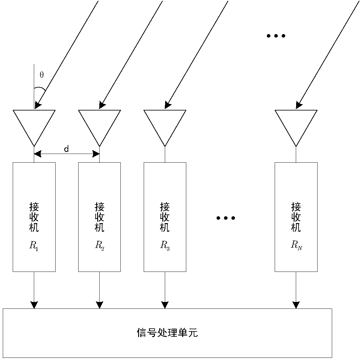
[0026] Fix the receiving channel array on the turntable, and generally only allow the turntable to rotate in the horizontal direction, so the array to be corrected should be consistent with the horizontal direction. by figure 1 The one-dimensional array shown is an example. If the coverage range of the radar in azimuth is -30°~+30°, the rotation range of the turntable should be about -20°~+20° (0° is the direction of the signal source). Due to the relative relations...


PUM


Abstract

The invention relates to a correction method for a radar receiving channel array. According to the method, the amplitudes and phase data of the receiving channel array at multiple angles are firstly recorded, and then amplitude and phase correction is carried out. The amplitude correction value is obtained through the method of averaging amplitude measurement values of the multiple angles. According to the calculation of the phase correction value, a phase reference channel is selected firstly, the theoretical phase deviation value of the reference channel is subtracted from the phase measurement value of each angle, bad values are removed, the residual data are averaged, then the phase deviation value is obtained, and the phase correction value is further obtained.

Description

technical field [0001] The invention relates to a correction method for a radar receiving channel array, which belongs to the field of signal and signal processing. Background technique [0002] A phased array radar antenna system generally includes multiple receiving channels. Since it is difficult to ensure that the electrical characteristics of all channels are consistent during the production process, this will cause differences in parameters such as bandwidth, gain, phase, delay characteristics, and noise figure of each channel. So when the same signal enters the channel, each channel will produce a different output signal. This will affect the beam shape after digital beamforming (DBF) of phased array radar, and directly affect the angle measurement accuracy of the target; at the same time, the inconsistency between channels will increase the sidelobe level, thereby reducing the signal detection capability of the radar. Therefore, in the application of phased array ra...

Claims


Application Information

Patent Timeline
IPC IPC(8): G01S7/40
CPCG01S7/4021
Inventor 李慧敏马汉清于贵龙高剑王毅
Owner CNGC INST NO 206 OF CHINA ARMS IND GRP
Why Eureka
Try Eureka