

Portable card reader
A card reader and portable technology, which is applied in the field of card readers, can solve the problems of easy breakage, space occupation, and unsophisticated appearance, and achieve the effects of reducing occupied space, avoiding antenna breakage, and improving seismic performance
- Summary
- Abstract
- Description
- Claims
- Application Information
AI Technical Summary
Problems solved by technology
Method used
Image

Examples
Embodiment
[0034] Such as Figures 1 to 5 As shown, only its structure is illustrated to illustrate its principle, and the actual structure can be designed by those of ordinary skill in the art.
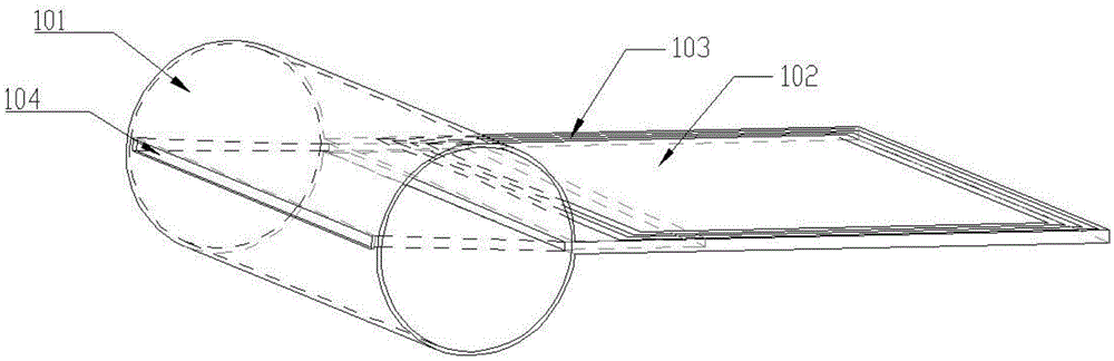
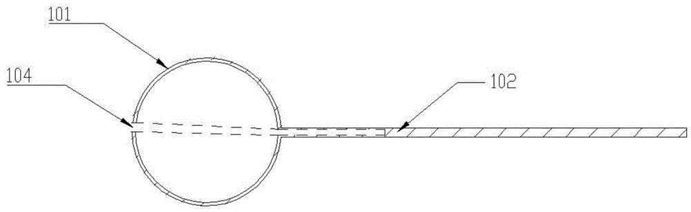
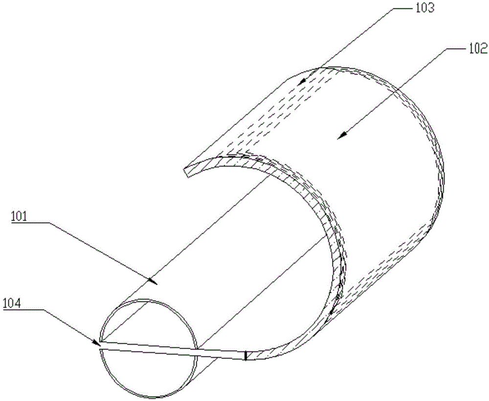
[0035] Such as Figures 1 to 5 As shown, the present invention provides a portable card reader, which is characterized in that it includes a circuit, a support shaft 101, and a flexibly deformable antenna panel 102 connected to the support shaft 101, wherein the flexibly deformable antenna panel 102 connected to the support shaft 101 The panel 102 is provided with a flexibly deformable antenna coil 103, and the flexibly deformable antenna coil 103 is electrically connected to the circuit for transmitting or receiving information. The antenna panel 102 is provided with a first slot, and the side wall of the antenna panel 102 is provided with a The opening of the first card slot, the first card slot extends to the inside of the antenna panel 102 . ;
[0036] in, figure 1 , 2 It is a schemati...
Embodiment approach
[0060] Such as Figure 4 As shown, the portable card reader is a contact card reader, and the contact card is inserted into the card reader from the card slot 104, and the card slot 104 extends to the inside of the flexible panel 102, and is positioned by the card position part in the card slot 104, so that The electronic chip on the contact card is contacted and connected with the card reader module in the card slot 104 to realize the information interaction between the card reader and the contact card;
[0061] Such as Figure 5 As shown, the portable card reader is a non-contact card reader. When the non-contact card reader is in a non-working state, the flexible antenna panel 102 can be accommodated and wound inside the support shaft 101. When the non-contact card reader When work is required, the flexible antenna panel 102 can be unfolded into a flat state, and an antenna coil is arranged inside the flexible antenna panel 102, which can exchange information with a non-co...
PUM
 Abstract
Description
Claims
Application Information