Power regulation circuit and ultrasonic tooth cleaner power regulation method

A technology of power adjustment and ultrasonic wave, applied in cleaning methods and appliances, cleaning methods using liquid, cleaning teeth, etc., can solve problems such as reducing the experience effect, reducing the service life of the dental scaler, and large heat generation of the voltage modulation unit, to improve Adjust speed, output soft effect

Active Publication Date: 2015-07-08
GUILIN WOODPECKER MEDICAL INSTR
View PDF6 Cites 5 Cited by
  • Summary
  • Abstract
  • Description
  • Claims
  • Application Information

AI Technical Summary

Problems solved by technology

In the traditional way, the output power is adjusted by changing the duty cycle of the ultrasonic signal, but in this way, the voltage modulation unit generates a lot of heat, which will greatly reduce the life of the scaler and reduce the user experience.

Method used


Image

  • Power regulation circuit and ultrasonic tooth cleaner power regulation method
  • Power regulation circuit and ultrasonic tooth cleaner power regulation method

Examples


Embodiment 1

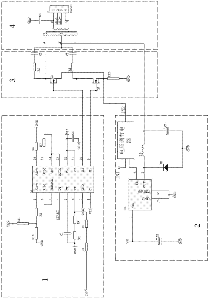
[0021] Embodiment 1, a power regulation circuit, will be combined below figure 1 A power regulation circuit provided in this embodiment is described in detail.

[0022] Such as figure 1 As shown, a schematic structural diagram of a power regulation circuit, including an ultrasonic signal generation unit 1, a drive voltage regulation unit 2, a voltage modulation unit 3 and an ultrasonic transformer unit 4; the control signal is connected through the input terminal of the ultrasonic signal generation unit 1, The output end of the ultrasonic signal generation unit 1 is connected to the input end of the voltage modulation unit 3, the output end of the driving voltage adjustment unit 2 is connected to the input end of the ultrasonic transformer unit 4, and the voltage modulation unit 3 is connected to the input end of the ultrasonic transformer unit 4. The ultrasonic transformer unit 4 is connected, and the output end of the ultrasonic transformer unit 4 is connected to an externa...

Embodiment 2

[0035] Embodiment 2. A method for adjusting the power of an ultrasonic dental scaler. The method for adjusting the power of an ultrasonic dental scaler provided in this embodiment will be described in detail below.

[0036] A method for adjusting the power of an ultrasonic dental scaler, comprising:

[0037] Step 1: The ultrasonic signal generation unit 1 receives an external control signal, generates an ultrasonic signal according to the control signal and outputs it to the voltage modulation unit 3;

[0038] Step 2: The voltage modulation unit 3 obtains a sampling voltage and outputs it to the driving voltage adjustment unit 2;

[0039] Step 3: The driving voltage adjustment unit 2 receives the sampling voltage signal output by the voltage modulation unit 3, generates an intermediate voltage signal according to the sampling voltage signal and outputs it to the ultrasonic transformer unit 4;

[0040] Step 4: The ultrasonic transformer unit 4 receives the intermediate voltage...


PUM


Abstract

The invention relates to a power regulation circuit and an ultrasonic tooth cleaner power regulation method. The power regulation circuit comprises an ultrasonic signal generating unit, a driving voltage regulating unit, a voltage modulating unit and an ultrasonic transformer unit; a control signal accesses through the input end of the ultrasonic signal generating unit, the output end of the ultrasonic signal generating unit is connected with the input end of the voltage modulating unit, the output end of the driving voltage regulating unit is connected with the input end of the ultrasonic transformer unit, the voltage modulating unit is connected with the ultrasonic transformer unit, and the output end of the ultrasonic transformer unit is connected to an external driving device. According to the power regulation circuit and the ultrasonic tooth cleaner power regulation method, the calorific value of a tooth cleaner is greatly reduced in the work process, a user can adjust the power of the tooth cleaner according to different parts, the best cleaning effect is achieved, the output of the ultrasonic tooth cleaner is softer, and therefore patients are more comfortable in the therapeutic process.

Description

technical field [0001] The invention relates to the field of electronic control, in particular to a power regulating circuit and a power regulating method for an ultrasonic dental scaler. Background technique [0002] The principle of the ultrasonic scaler is to use the working tip of ultrasonic vibration to contact the surface of the tooth, and achieve the purpose of removing tartar and plaque on the surface of the tooth through physical methods. Ultrasonic scalers need to use ultrasonic transducers to convert electrical energy into mechanical energy of ultrasonic vibration. Combined with the needs of users, the output power of the scaler needs to be adjustable to meet the needs of different users and the clarity of different parts to obtain better cleaning effects . In the traditional way, the output power is adjusted by changing the duty cycle of the ultrasonic signal, but in this way, the voltage modulation unit generates a lot of heat, which will greatly reduce the lif...

Claims


Application Information

Patent Timeline
Patent Type & Authority Applications(China)
IPC IPC(8): A61C17/20
CPCA61C17/20A61C17/221
Inventor 吴勋贤陈泽荣林剑华
Owner GUILIN WOODPECKER MEDICAL INSTR
Why Eureka
Try Eureka