Power distribution and combination machine based on ultra wide band coaxial impedance transformer

A technology of impedance converter and power combiner, which is applied in the direction of waveguide devices, connecting devices, electrical components, etc., can solve the problems of large radio frequency loss, large structure size, difficult module miniaturization, and reduced output power, etc., to achieve wide coverage frequency band , saving cost and space, size reduction effect

Active Publication Date: 2015-07-08
CHINA ELECTRONIS TECH INSTR CO LTD
View PDF6 Cites 6 Cited by
  • Summary
  • Abstract
  • Description
  • Claims
  • Application Information

AI Technical Summary

Problems solved by technology

The traditional planar microstrip line power division and synthesis scheme has the advantages of simple structure, easy fabrication and convenient integration with circuits, but in the frequency band of 500KHz-3GHz, due to the low frequency and ultra-wideband, the overall structure size of microstrip power division and synthesis It is not easy to miniaturize the module, and the large structure size brings large radio frequency loss, which greatly reduces the output power
The coaxial balun power division and synthesis scheme realizes four-way synthesis as a whole. There is no microstrip matching in the whole process, which greatly reduces the structure size and radio frequency loss, but the number of channels is limited to four.

Method used


Image

  • Power distribution and combination machine based on ultra wide band coaxial impedance transformer
  • Power distribution and combination machine based on ultra wide band coaxial impedance transformer
  • Power distribution and combination machine based on ultra wide band coaxial impedance transformer

Examples


Embodiment Construction

[0026] Below in conjunction with accompanying drawing and embodiment the present invention will be further described:

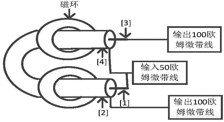
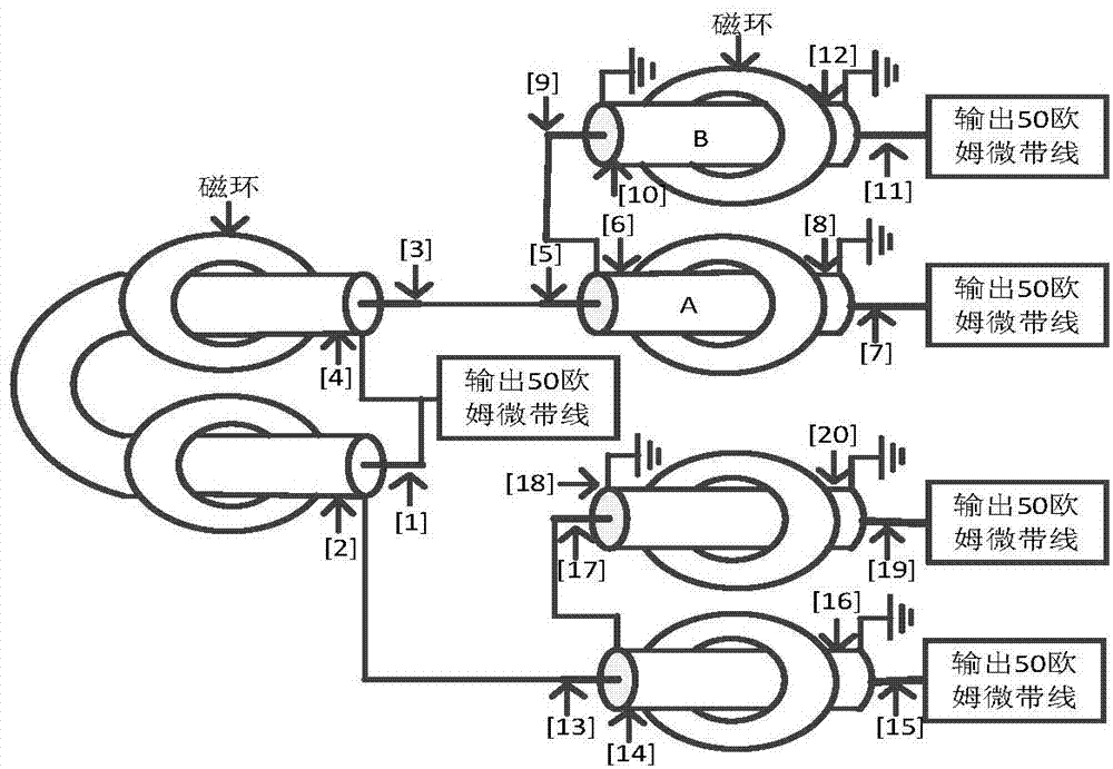
[0027] As shown in Figure 1, the one-to-four coaxial impedance converter includes a coaxial line on which a ferrite magnetic ring is arranged; the inner conductor 1 at one end of the coaxial line and the outer conductor at the other end 4 are connected, and connected to the microstrip line whose characteristic impedance at the input end is α, the outer conductor 2 is connected to the output I road, and the inner conductor 3 is connected to the output II road. Among them, taking α as 50 ohms as an example, the power distribution and combiner composed of the following one-to-coaxial impedance converter and one-to-four coaxial impedance converter and one-to-coaxial impedance converter are all the same as one-to-four The output impedance of the coaxial impedance converter is matched.

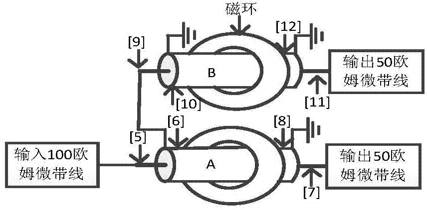
[0028] A one-to-coaxial impedance converter, including two coaxial lines A an...


PUM


Abstract

The invention discloses a power distribution and combination machine based on an ultra wide band coaxial impedance transformer. The power combination machine comprises a one-to-four coaxial impedance transformer, outputs of the one-to-four coaxial impedance transformer are a first output circuit and a second output circuit, the first output circuit and the second output circuit are each connected with a one-to-one coaxial impedance transformer, the one-to-four coaxial impedance transformer is connected with the one-to-one coaxial impedance transformers in series, and power distribution of four circuits is achieved; after the power distribution is carried out on the four circuits, each circuit is connected to a coaxial line coaxial balun with an alpha characteristic impedance, each coaxial balun is connected with a push-pull amplifier, and combination of four stages of push-pull output power is achieved; or after the power distribution is carried out on the four circuits, the circuits are connected to coaxial line coaxial baluns Z1 which are matched with output impedance of the one-to-one coaxial impedance transformers and have the same characteristic impedance; each coaxial balun Z1 is distributed into two circuits of constant amplitude inversion signals by the power distribution; each circuit of each coaxial balun Z1 is distributed into two circuits, and finally combined output is carried out through coaxial baluns Z2 which has the same structure with the coaxial baluns Z1.

Description

technical field [0001] The invention belongs to the field of power combiners, in particular to a power distribution and combiner based on an ultra-wideband coaxial impedance converter. Background technique [0002] Power amplifiers are widely used in the fields of industrial processing, radar, guidance and communication, etc., and higher and higher requirements are put forward for the bandwidth, gain and output power of power amplifiers. For example: in the 500KHz-3GHz frequency band, for the solid-state power amplifier chip whose port impedance is not internally matched to 50 ohms, the power synthesis mostly uses a coaxial balun combined with a microstrip matching push-pull output, but it is limited to the first-stage push-pull output. For a solid-state power amplifier chip whose port impedance is matched to 50 ohms, the microstrip power division and synthesis scheme has a large structure and large loss, and it is not easy to miniaturize the module and increase the output p...

Claims


Application Information

Patent Timeline
Patent Type & Authority Applications(China)
IPC IPC(8): H01P1/213H01P5/16
Inventor 朴智棋宁曰民刘金现孙国泉
Owner CHINA ELECTRONIS TECH INSTR CO LTD
Why Eureka
Try Eureka