a pneumatic elevator

A pneumatic elevator and hoistway technology, which is applied in the elevator field, can solve the problems of noise pollution of the car and weak seals at the guide rails, and achieve the effects of improving comfort, reducing processing costs, and improving sealing reliability.

Active Publication Date: 2018-06-01
KUSN KOYO ELEVATOR
View PDF5 Cites 1 Cited by
  • Summary
  • Abstract
  • Description
  • Claims
  • Application Information

AI Technical Summary

Problems solved by technology

[0004] The invention provides a pneumatic elevator to solve the problems of weak sealing at the guide rail of the existing pneumatic elevator and serious noise pollution of the car

Method used


Image

  • a pneumatic elevator
  • a pneumatic elevator
  • a pneumatic elevator

Examples


Embodiment Construction

[0023] In order to describe the technical solution of the above invention in more detail, specific examples are listed below to demonstrate the technical effect; it should be emphasized that these examples are used to illustrate the present invention and not limit the scope of the present invention.

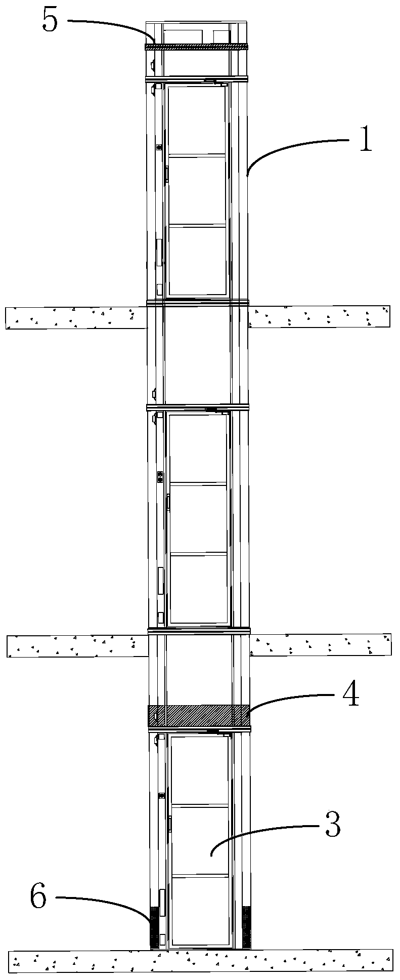
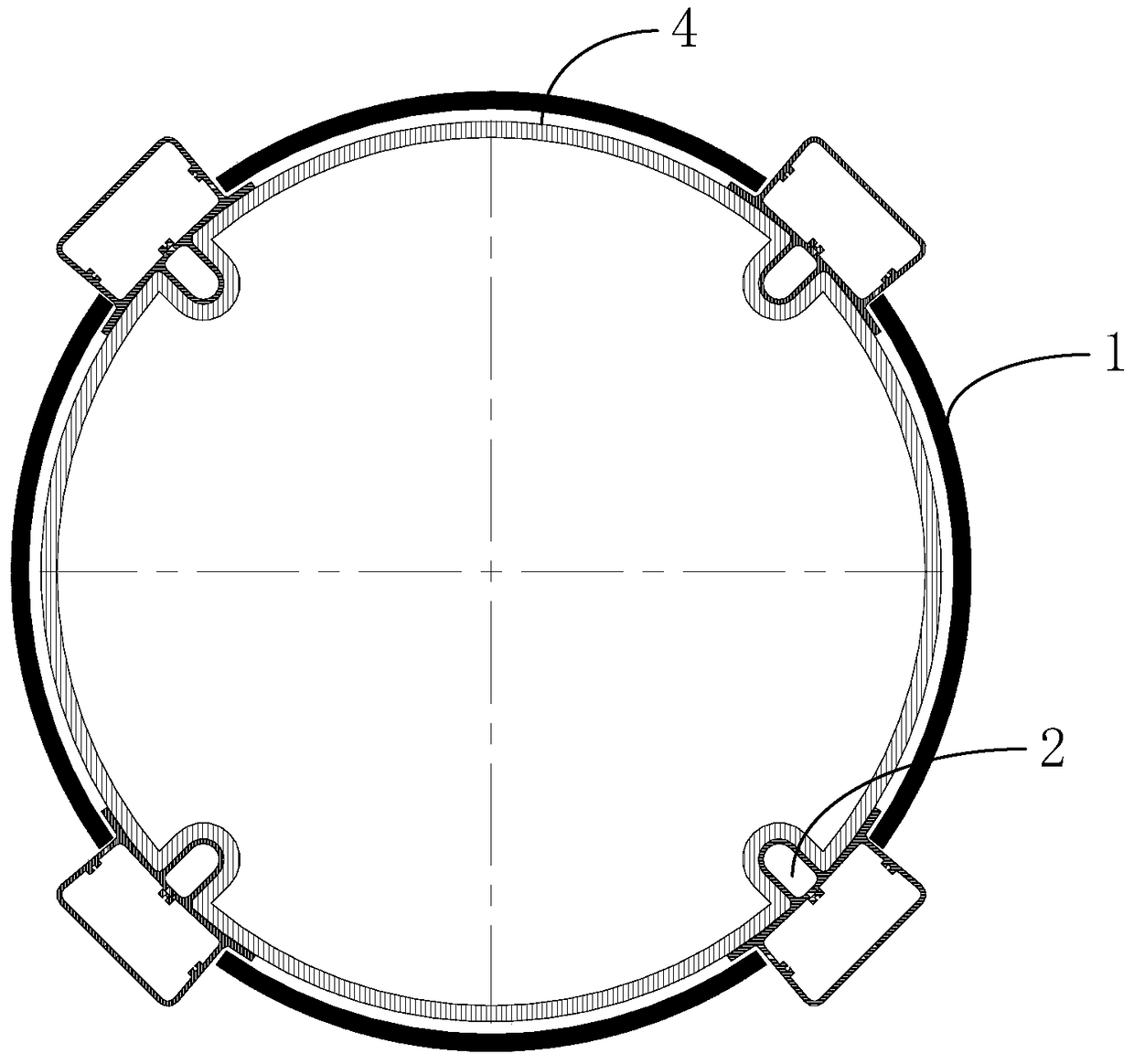
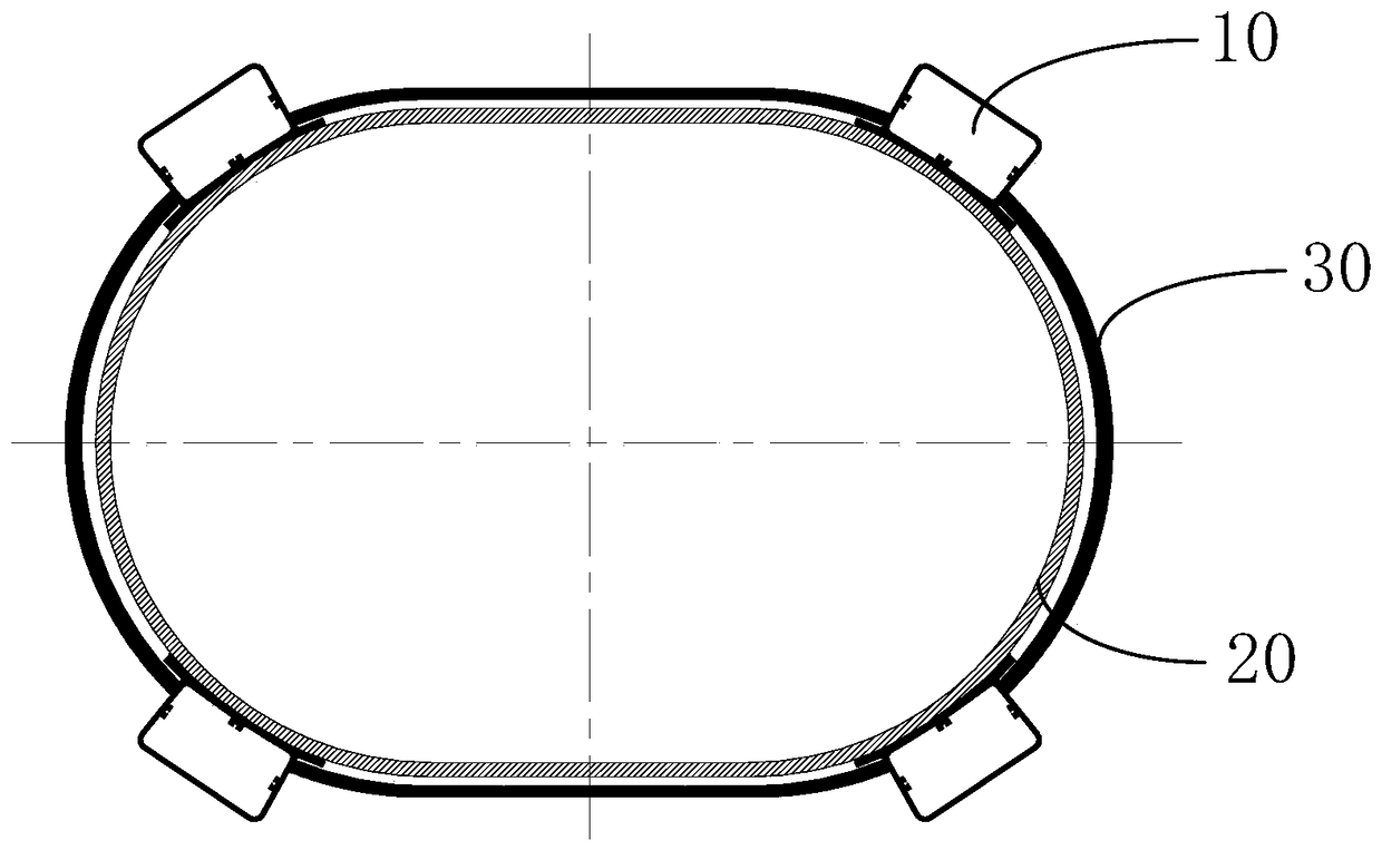
[0024] A kind of pneumatic elevator provided by the present invention, please refer to Figure 3 to Figure 5 , and combined with figure 1 , comprising a shaft 30, a car and a vacuum motor, the top of the car is provided with a car seal ring 20, the top of the shaft 30 is provided with a top seal ring, the car seal ring 20, the top seal ring and the shaft 30 The side wall forms a closed space, and the vacuum motor extracts or releases the air in the closed space to drive the pneumatic elevator car to go up and down. The contour matches the shape of the hoistway 30 and the car is confined within the hoistway 30 . The present invention uses the shape of the hoistway 30 itself to l...


PUM


Abstract

The invention relates to a pneumatic lift. The pneumatic lift comprises a shaft way, a lift car and a vacuum motor. A lift car seal ring is arranged on the top of the lift car. A top layer seal ring is arranged on the top of the shaft way. The lift car seal ring, the top layer seal ring and the side wall of the shaft way form a sealed space. The vacuum motor extracts or discharges air in the sealed space and drives the lift car of the pneumatic lift to move up and down. The overlooking outline of the shaft way is not a perfect circle. The outer outline of the lift car is matched with the shape of the shaft way. The lift car is limited in the shaft way. According to the pneumatic lift, the lift car is limited and guided through the shape of the shaft way, the lift car is prevented from rotating, the influence of a protruding guide rail on a seal effect is avoided, and the problem that noise is generated by air flow due to a poor seal effect is solved.

Description

technical field [0001] The invention relates to the field of elevators, in particular to a pneumatic elevator. Background technique [0002] As a new type of elevator technology, pneumatic elevator has become a hot technology in the elevator industry due to its characteristics of no counterweight, no bottom pit and easy installation. At present, the structure of the pneumatic elevator is as follows: figure 1 and figure 2 As shown, it mainly includes: circular hoistway 1, guide rail 2, car 3 and vacuum motor, car sealing ring 4, top layer sealing ring 5 and the side wall of hoistway 1 form a closed space, and the vacuum motor is used to pump air, so that all The pressure in the above-mentioned confined space decreases, and the bottom of the car 3 communicates with the external atmospheric pressure through the bottom air inlet 6, so that the vacuum motor can be used to form a pressure difference between the upper part of the car top and the lower part of the car bottom of t...

Claims


Application Information

Patent Timeline
Patent Type & Authority Patents(China)
IPC IPC(8): B66B9/04B66B11/02B66B7/00
CPCB66B7/00B66B9/04
Inventor 徐晶任维安王琰
Owner KUSN KOYO ELEVATOR
Why Eureka
Try Eureka