Sanitary installation part and component of a sanitary fitting

A technology of sanitary built-in parts and adjusting components, which is applied in the field of sanitary built-in parts, and can solve problems such as increased residence time, useless water consumption, and prolonging the time for hot water to flow out

Inactive Publication Date: 2015-09-30
NEOPERL
View PDF8 Cites 8 Cited by
  • Summary
  • Abstract
  • Description
  • Claims
  • Application Information

AI Technical Summary

Problems solved by technology

[0005] Known flow regulators cause increased residence time of water or other liquid media in water pipes
Especially in hot water pipes which are not permanently kept at temperature and are cooled between periods of use, this can lead to a bacterial load in particular of the water or other media being conveyed
Furthermore, in cooled hot water pipes, the time from opening the fitting to the flow of hot water is prolonged (depending on the length of the cooled line), which annoys the user and leads to useless water consumption

Method used


Image

  • Sanitary installation part and component of a sanitary fitting
  • Sanitary installation part and component of a sanitary fitting
  • Sanitary installation part and component of a sanitary fitting

Examples


Embodiment Construction

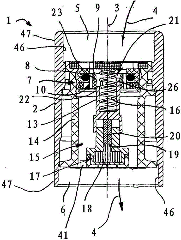
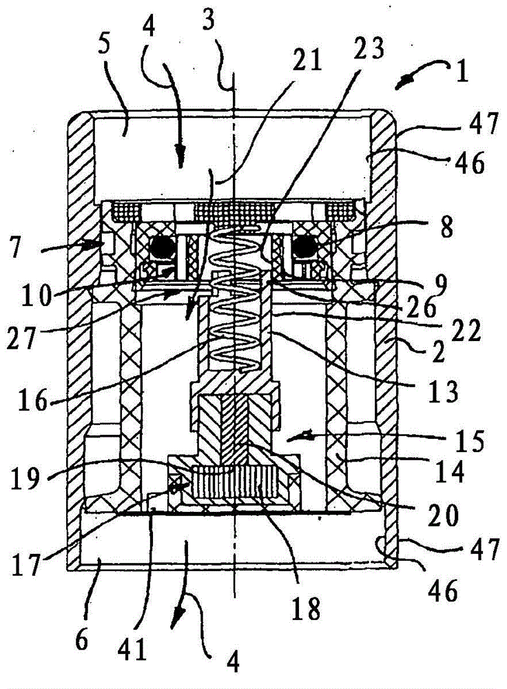
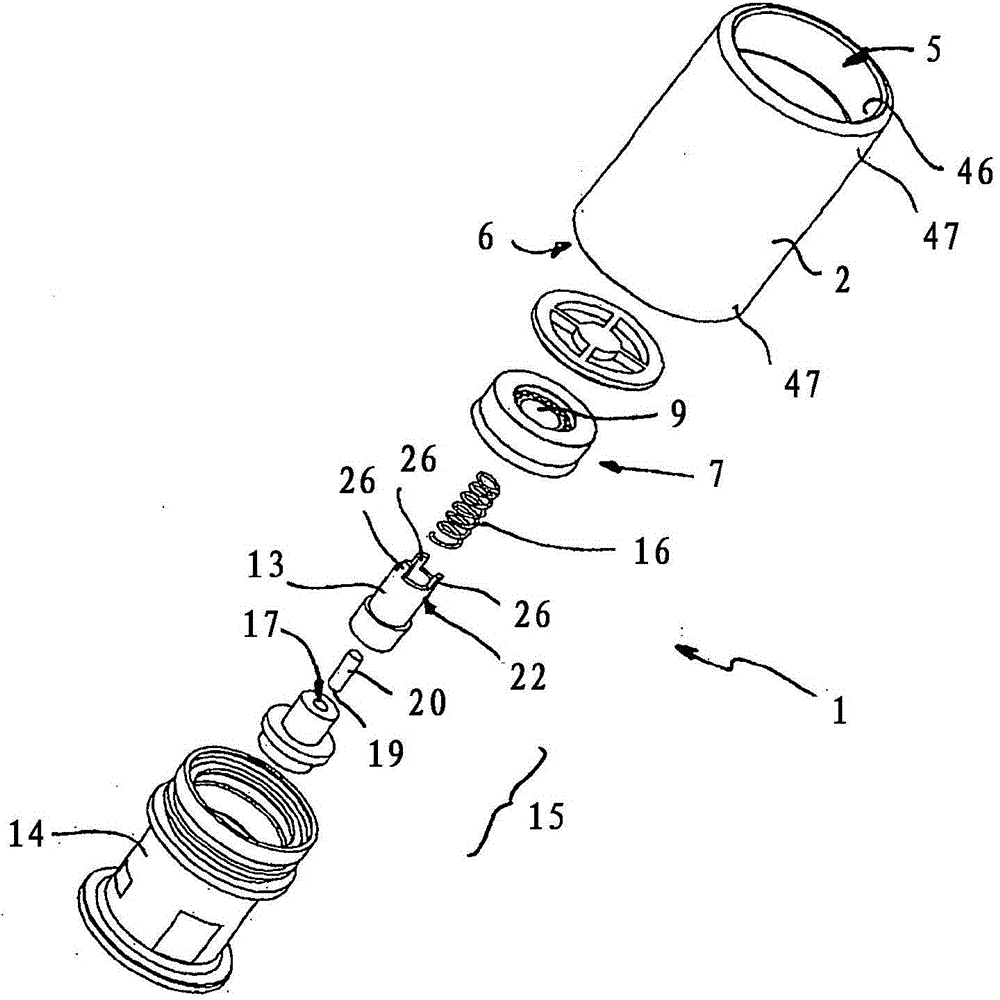
[0084] figure 1 An axial sectional view of the sanitary insert according to the invention, identified with 1 in the housing, is shown.

[0085] The insert 1 is formed with a tubular insert sleeve 2 as a cartridge, in particular a plug-in cartridge.

[0086] In the example shown, the axis 3 of the cylindrical fitting sleeve 2 defines a flow path 4 whose flow direction is figure 1 The center extends between the inlet 5 and the outlet 6 from top to bottom.

[0087] Between the inlet 5 and the outlet 6 , a functional unit 7 is formed in the throughflow path 4 , which implements the volume flow dependence of the flow regulating function in a manner known per se by means of a barrier body 8 (O-ring). Depending on the pressure exerted on the inlet 5 or depending on the pressure drop across the functional unit 7 between the inlet 5 and the outlet 6, the barrier body 8 is pressed against the receiving part 9 to different extents, so that the cross-sectional area and the pressure Rel...


PUM


Abstract

In a sanitary installation part (1) which, along with a functional unit (7), forms a quantity regulator, it is proposed that a regulating element (13), which can be adjusted along an adjustment path, be coupled to a temperature‑sensitive drive unit (15) such that different regulating positions of the regulating element (13) are set in dependence on the temperature of the medium flowing through the installation part (1), wherein the different regulating positions realize in each case different volume‑flow dependencies (11, 12, 45, 48) and / or flow resistances (cf. figure 1).

Description

technical field [0001] The invention relates to a sanitary insert having a functional unit arranged along a flow path, which is implemented in such a way that a pressure-dependent volume flow is defined as a volume flow dependence. [0002] The invention also relates to a sanitary fitting assembly. [0003] The invention finally relates to a method for controlling the flow of a flowing medium, in particular flowing water. Background technique [0004] Such inserts are known in sanitary technology as flow regulators and serve to save water. [0005] Known flow regulators cause an increase in the residence time of water or other liquid media in the water pipes. Especially in hot water pipes which are not kept at a constant temperature and are cooled between periods of use, this can lead to a bacterial load, in particular of the water or other medium being conveyed. Furthermore, in cooled hot water pipes, the time from opening the fitting to the flow of hot water is prolonge...

Claims


Application Information

Patent Timeline
Patent Type & Authority Applications(China)
IPC IPC(8): E03C1/04F16K31/00G05D7/01
CPCG05D7/012E03C1/041G05D23/022F16K31/002E03C1/08E03C2001/026E03C1/01F16K31/02E03C1/04F16K31/00F16K3/08G05D23/08
Inventor M·滕佩尔C·维斯
Owner NEOPERL
Why Eureka
Try Eureka