Warning method and system for locomotive brake system

A technology for braking systems and locomotives, applied in railway braking systems, railway signals and safety, etc., can solve problems affecting the safety and stability of braking systems, potential safety hazards of locomotive operation, and failure to obtain the operating status of locomotive braking systems in time , to achieve the effect of easy operation and simple method

Active Publication Date: 2015-12-23
QINGDAO SRI TECH CO LTD
View PDF8 Cites 0 Cited by
  • Summary
  • Abstract
  • Description
  • Claims
  • Application Information

AI Technical Summary

Problems solved by technology

However, there is currently a lack of status display and fault query for the locomotive braking system. Therefore, the operator cannot obtain the current operating status of the locomotive braking system in time, and even cannot take corresponding measures in time when the locomotive braking system fails, which affects the operation of the locomotive braking system. The safety and stability of the driving system will bring hidden dangers to the operation safety of the locomotive

Method used


Image

  • Warning method and system for locomotive brake system
  • Warning method and system for locomotive brake system

Examples


Embodiment 1

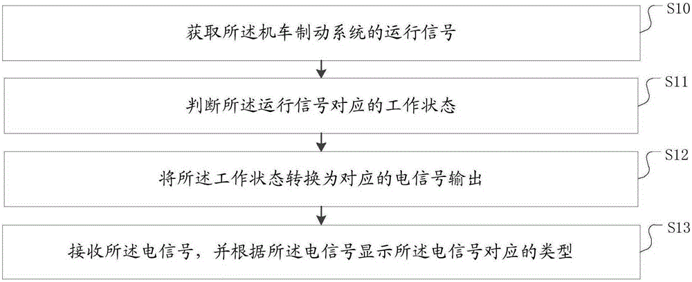
[0045] figure 1 It is a flowchart of a warning method for a locomotive braking system provided by the present invention. include:

[0046] S10: Obtain an operation signal of the braking system of the locomotive.

[0047] S11: Determine the working state corresponding to the running signal.

[0048] S12: Convert the working state into a corresponding electrical signal output.

[0049] S13: Receive the electrical signal, and display a type corresponding to the electrical signal according to the electrical signal.

[0050] The operating signal of the locomotive braking system can reflect the current operating state of the brake, thereby reflecting the current operating state of the locomotive braking system. For example, when the brake fails, the braking system can be known by obtaining the operating signal of the locomotive braking system. Motivation malfunctioned. Therefore, in the present invention, the operation signal of the braking system of the locomotive is acquired ...

Embodiment 2

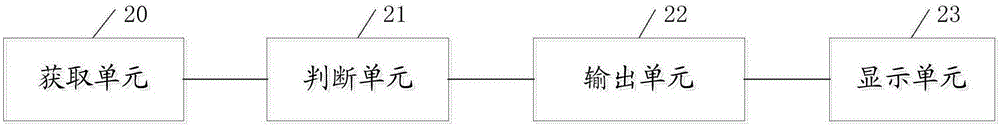
[0064] figure 2 It is a structural diagram of a warning system of a locomotive braking system provided by the present invention. Warning systems for locomotive braking systems, including:

[0065] An acquisition unit 20, configured to acquire an operating signal of the locomotive braking system;

[0066] Judging unit 21, used to judge the working state corresponding to the running signal;

[0067] The output unit 22 is used to convert the working state into a corresponding electrical signal output;

[0068] The display unit 23 is configured to receive the electrical signal, and display the type corresponding to the electrical signal according to the electrical signal.

[0069] The operating signal of the locomotive braking system can reflect the current operating state of the brake, thereby reflecting the current operating state of the locomotive braking system. For example, when the brake fails, the braking system can be known by obtaining the operating signal of the loco...


PUM


Abstract

The invention discloses a warning method for a locomotive brake system. The warning method comprises the following steps: acquiring an operation signal of the locomotive brake system; judging a working state corresponding to the operation signal; converting the working state into a corresponding electric signal for outputting; and receiving the electric signal, and displaying a type corresponding to the electric signal according to the electric signal. According to the method, the working state corresponding to the locomotive brake system is judged by virtue of the operation signal of the locomotive brake system, and the corresponding electric signal is output after the working state is determined, so that the corresponding type is displayed according to the electric signal, and therefore, a driver can determine the working state of the locomotive brake system. The warning method is simple, easy to operate and capable of realizing warning for the locomotive brake system. Besides, the invention further discloses a system corresponding to the method.

Description

technical field [0001] The invention relates to the technical field of braking of electric control controllers for railway locomotives, in particular to a warning method and system for a locomotive braking system. Background technique [0002] The braking system of rail locomotives is a key component to ensure the safety of rail transportation, and the safety, reliability and stability of the braking system are particularly important. The working status display and fault query of the braking system increase the driving safety of the locomotive to a certain extent. However, there is currently a lack of status display and fault query for the locomotive braking system. Therefore, the operator cannot obtain the current operating status of the locomotive braking system in time, and even cannot take corresponding measures in time when the locomotive braking system fails, which affects the operation of the locomotive braking system. The safety and stability of the driving system w...

Claims


Application Information

Patent Timeline
Patent Type & Authority Applications(China)
IPC IPC(8): B61H11/00B61L23/00
Inventor 黄蕊武小平万建兵白洪民胡斌陈杰
Owner QINGDAO SRI TECH CO LTD
Why Eureka
Try Eureka