fuel injector

A fuel injector and injector technology, which is applied to fuel injection devices, special fuel injection devices, charging systems, etc., can solve the problems of slow opening transients and slow closing transients, etc.

Active Publication Date: 2020-03-20
VTESCO TECH GMBH
View PDF12 Cites 0 Cited by
  • Summary
  • Abstract
  • Description
  • Claims
  • Application Information

AI Technical Summary

Problems solved by technology

However, too much damping results in slower turn-on transients and slower turn-off transients, which is not desirable

Method used


Image

  • fuel injector
  • fuel injector
  • fuel injector

Examples


Embodiment Construction

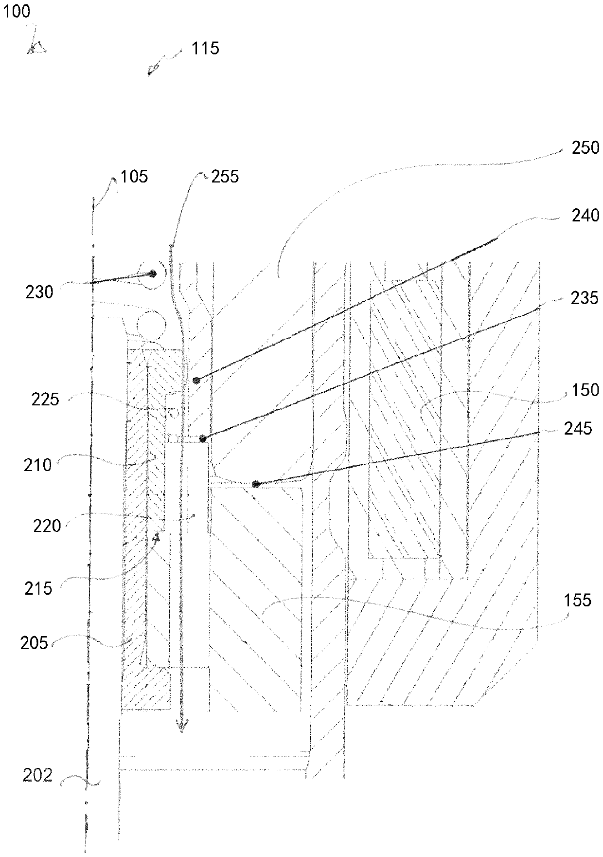
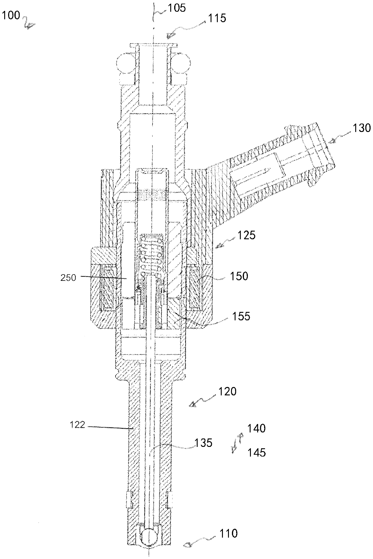
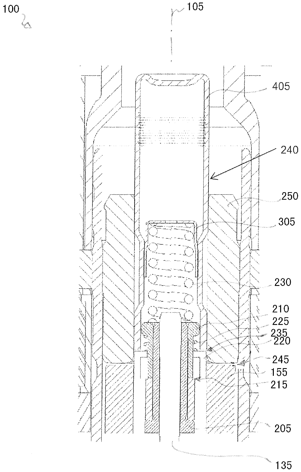
[0029] figure 1 An injector 100 for injecting fuel into a combustion engine according to a first exemplary embodiment is shown in longitudinal section.

[0030] Injector 100 has a longitudinal axis 105, a nozzle end 110, and an opposing supply end 115, sometimes referred to as a fuel inlet end and a fuel outlet end, respectively. The injector 100 includes a valve 120 and an actuator 125 for operating the valve 120 . Actuator 125 is an electromagnetic actuator powered through connector 130 . When power is supplied to connector 130 , fuel flows from supply end 115 through valve 120 and is injected from injector 100 at nozzle end 110 .

[0031] In the illustrated embodiment, valve 120 includes a valve needle 135 movable along axis 105 between an open position 140 in which valve 120 is open and a closed position 145 in which no fuel may pass through valve 120 . The valve needle 135 is accommodated in the cavity of the valve body 122 and is axially displaceable in a reciprocatin...


PUM


Abstract

The present invention discloses a fuel injector (100). It comprises a valve (120) having a valve needle (135) movable along a longitudinal axis (105) between an open position (140) and a closed position (145), In order to open or close the valve (120); the actuator (125), the actuator (125) includes an armature (155) and a pole piece (250), the armature (155) can move axially and can Operated to mechanically interact with said valve needle (135) such that said valve needle (135) is moved towards said pole piece (250) by movement of said armature (155) in an axial direction towards said An open position (140) moves; and a first spring (220) for biasing the armature (155) in an axial direction away from the pole piece (250). The first spring (220) is configured and operable to stop the movement of the armature (155) by its elastic force when the valve needle (135) is located at the open position (140).

Description

technical field [0001] The present invention relates to fuel injectors. More particularly, it relates to a fuel injector for use with a combustion engine in a motor vehicle. Background technique [0002] A fuel injector for injecting fuel into a combustion engine includes a valve that can be opened against a spring force by an electrically driven actuator. Different designs are known in the art including electromagnetic or piezoelectric actuators, digital or servo modes and actuators for different fuel types such as gasoline or diesel. [0003] US 2006 / 0255185 A1 shows a fuel injector with an electromagnetic actuator, wherein the valve comprises a valve needle and the valve opens when the valve needle moves in the direction of the nozzle of the injector. [0004] The amount of fuel that passes through the injector generally depends on when the actuator is driven. A flow curve showing the relationship between drive time and throughput generally has three consecutive region...

Claims


Application Information

Patent Timeline
Patent Type & Authority Patents(China)
IPC IPC(8): F02M61/10F02M51/06
CPCF02M51/0671F02M51/0664F02M51/0685F02M2200/304F02M2200/306F02M61/20F02M51/0614F02M41/00F02M61/10
Inventor I.伊佐M.梅基
Owner VTESCO TECH GMBH
Why Eureka
Try Eureka