A Three-phase Reactive Power Unbalance Compensation Method

A technology of power unbalance and compensation method, applied in reactive power adjustment/elimination/compensation, reactive power compensation and other directions, can solve the problems of complex principle, unbalanced reactive power compensation, low control accuracy, etc. The effect of high accuracy, high control accuracy and fast response speed

Active Publication Date: 2018-06-26
XIAN HIGH VOLTAGE APP RES INST CO LTD
View PDF4 Cites 0 Cited by
  • Summary
  • Abstract
  • Description
  • Claims
  • Application Information

AI Technical Summary

Problems solved by technology

The compensation capacity of FC is fixed, which can improve the average power factor, and often there is a large under-compensation or over-compensation; MSC can automatically switch in groups, and can automatically track the change of load reactive power in a stepwise manner, and the compensation effect is better than that of FC. , but the automatic switching delay is long, there are problems of input inrush current and arc removal, and the contactor and capacitor are easily damaged; TSC uses thyristor static switch to solve the problem of inrush current and arc, but it is still a step tracking; thyristor controllable reactance TCR has the function of continuously and quickly adjusting inductive reactive power, but the amount of harmonic generation is large, and a certain number of filtering devices need to be configured; SVG has a bidirectional compensation function for continuously and quickly adjusting inductive and capacitive reactive power, and will not generate harmonics. It can also compensate the harmonics at the same time, and it is the best reactive power compensation device at present, but the relative cost is high and the cost performance is low.
There is also a composite power quality adjustment device, which is composed of multiple sets of TSCs and a set of SVGs, which can make up for each other's shortcomings and integrate the advantages of the two, and can realize rapid and continuous adjustment of large-capacity reactive power. Wave control and unbalanced reactive power compensation, but the compensation method is difficult to implement, the control accuracy is low, and the principle is complicated

Method used


Image

  • A Three-phase Reactive Power Unbalance Compensation Method
  • A Three-phase Reactive Power Unbalance Compensation Method
  • A Three-phase Reactive Power Unbalance Compensation Method

Examples


Embodiment Construction

[0026] The present invention will be further described in detail below in conjunction with specific embodiments, which are explanations of the present invention rather than limitations.

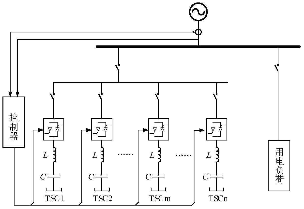
[0027] In this preferred example, the description is made by taking the capacitor in the TSC as an example. It can realize the unbalance compensation of reactive power compensation devices containing multiple sets of TSCs with phase-splitting compensation functions, such as figure 1 As shown, it is assumed that there are n groups of TSCs, and each group has the same capacity. Among them, m groups of TSCs have the function of replenishment. n-1,..., m, m, m+1,..., n after resection smoothly from front to back. Wherein, 1≤m


PUM


Abstract

The invention discloses a three-phase reactive power unbalance compensation method. An execution system comprises at least one group of capacitors capable of achieving division and compensation functions. The compensation method comprises the following steps: (1) collecting three-phase voltage and current values of a system power supply, calculating a reactive power value of each phase, and taking the minimal reactive power value as a reference value; (2) sequentially finding the difference between the reactive power value of each phase and the reference value, taking the comparative result of the difference value of each phase and a corresponding input threshold as a judgment condition of entering an input link, and if the different value of each phase is greater than the corresponding input threshold, entering the input link, or else, entering a removal link; (3) taking whether status words of dividing and compensating capacitors of which the input orders are set as the first group are completely input or not as the judgment condition of entering the removal link, and if so, entering the removal link, or else, entering an instruction sending link; and (4) in the sending link, taking the comparative result of the current status words of each group of capacitors and a corresponding backup word as the judgment condition of sending a switching instruction, if the current status words are consistent with the corresponding backup word, not sending the switching instruction, and if the current status words are not consistent with the corresponding backup word, driving split-phase switching.

Description

technical field [0001] The invention relates to the technical field of reactive power compensation, in particular to a three-phase reactive power unbalance compensation method. Background technique [0002] In the power grid, the operation of most loads (such as motors, electric arc furnaces, etc.) and network components (such as transformers, transmission lines, etc.) not only requires the power supply to provide active power, but also needs to provide corresponding reactive power. It is obviously unreasonable and impossible for these reactive powers to be provided by generators and transmitted over long distances. A reasonable method is to generate reactive power where reactive power needs to be consumed, which is reactive power compensation. Reactive power compensation is of great significance to the operation of power supply system and load. [0003] At present, the low-voltage reactive power compensation devices mainly include: fixed input shunt capacitor FC, parallel...

Claims


Application Information

Patent Timeline
Patent Type & Authority Patents(China)
IPC IPC(8): H02J3/18
CPCY02E40/30
Inventor 范伟强雷颖王弋飞李隆鹏万媛李罗李侠魏泉
Owner XIAN HIGH VOLTAGE APP RES INST CO LTD
Why Eureka
Try Eureka