FM pilot signal generation method and circuit

A pilot signal and signal technology, applied in the FM field, can solve the problems of not having such a high frequency, high power consumption, and high power, and achieve the effect of reducing power consumption and low power consumption

Active Publication Date: 2016-03-23
BEIJING HUNTERSUN ELECTRONICS CO LTD
View PDF13 Cites 4 Cited by
  • Summary
  • Abstract
  • Description
  • Claims
  • Application Information

AI Technical Summary

Problems solved by technology

[0004] At present, in the FM two-channel stereo transmission system, the 19kHz pilot frequency is mainly generated by fixed high-frequency crystal oscillators such as 24M/12M/7.6M. However, in some FM two-channel stereo transmission systems, the crystal oscillator does not High frequency, such as only 32.768kHz; therefore, the FM two-channel stereo transmission system for the low-frequency crystal oscillator mainly realizes the FM transmission frequency and the 19kHz pilot signal by setting two system PLLs (PhaseLockedLoop, phase-locked loop) G

Method used


Image

  • FM pilot signal generation method and circuit
  • FM pilot signal generation method and circuit
  • FM pilot signal generation method and circuit

Examples


Embodiment Construction

[0063] The following will clearly and completely describe the technical solutions in the embodiments of the present invention with reference to the accompanying drawings in the embodiments of the present invention. Obviously, the described embodiments are only some, not all, embodiments of the present invention. Based on the embodiments of the present invention, all other embodiments obtained by persons of ordinary skill in the art without making creative efforts belong to the protection scope of the present invention.

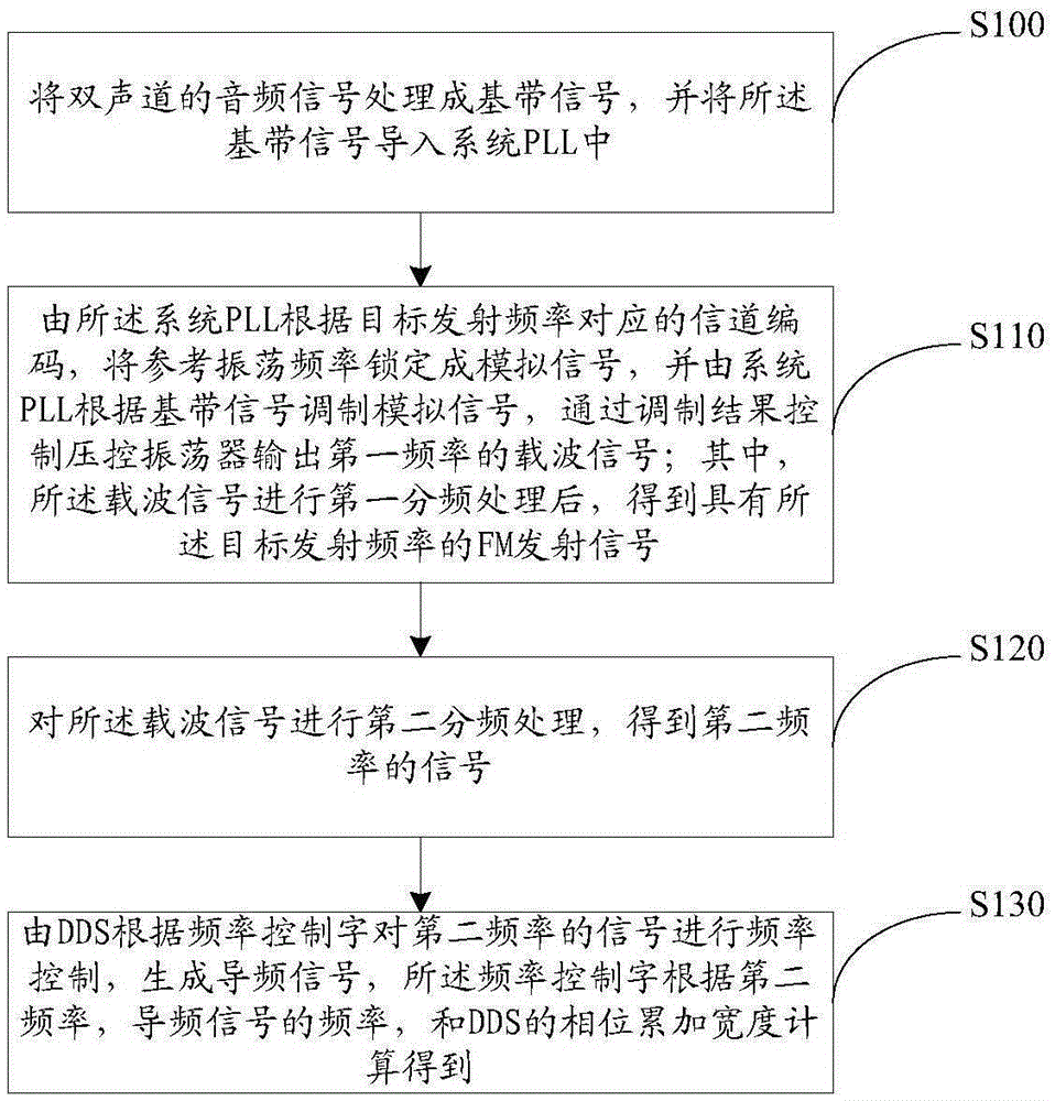
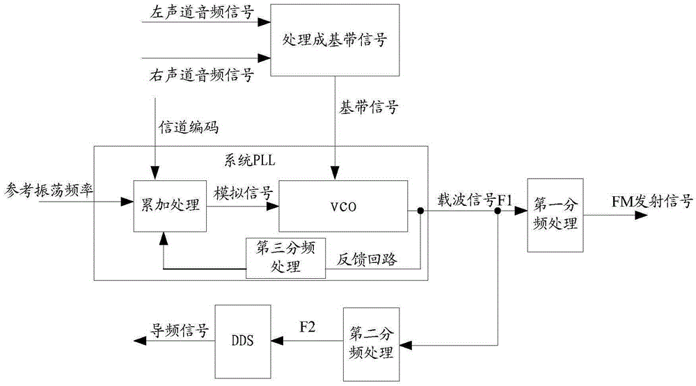
[0064] figure 2 The flowchart of the FM pilot signal generating method provided by the embodiment of the present invention, image 3 The schematic diagram of FM pilot signal generation provided for the embodiment of the present invention, combined with figure 2 and image 3 As shown, the FM pilot signal generation method provided by the embodiment of the present invention may include:

[0065] Step S100, processing the two-channel audio signal into a base...


PUM


Abstract

The application provides an FM (frequency modulation) pilot signal generation method and circuit, wherein the method comprises: processing a double-track audio signal into a baseband signal, and introducing the baseband signal into a system PLL, the system PLL being provided with a VCO; the system PLL locking a reference oscillation frequency to be a simulation signal according to the channel coding corresponding to a target emission frequency, modulating the simulation signal according to the baseband signal, and controlling the VCO to output the carrier wave signal of a first frequency according to a modulation result; performing first frequency division treatment on the carrier wave signal to obtain an FM emission signal of the target emission frequency; performing second frequency division treatment on the carrier wave signal to obtain a signal of a second frequency; and a DDS performing frequency controlling on the signal of a second frequency according to a frequency control word to generate a pilot signal. The FM pilot signal generation method and circuit are suitable for a low frequency crystal oscillator FM double-track stereo emission system, and can generate an FM emission signal and a pilot signal through the system PLL.

Description

technical field [0001] The invention relates to the technical field of FM (frequency modulation, frequency modulation), in particular to a method and circuit for generating an FM pilot signal. Background technique [0002] In FM stereo transmission, since stereo is more susceptible to signal interference than mono, the left channel signal L and the right channel signal R need to be algebraically coded, that is, sign1=L+R, sign2=L-R, composed of two independent The audio channel is used for transmission; sign1 is transmitted by the main channel as baseband audio, and the transmission frequency range is 30Hz to 15kH; sign2 is transmitted by the subcarrier signal, and the specific sign2 is transmitted on the 38kHz double-sided suppressed carrier (DSB-SC) signal through amplitude modulation. Occupies the frequency band 23kHz ~ 53kHz. When receiving stereo audio, it is necessary to receive the sign1 and sign2 signals, and calculate and restore the information of the left channel...

Claims


Application Information

Patent Timeline
IPC IPC(8): H04B1/04H04B1/76H04H20/48
CPCH04B1/04H04B1/0475H04B1/76H04H20/48
Inventor 尚潇洒钱永学苗俊涛杨祎陈建球
Owner BEIJING HUNTERSUN ELECTRONICS CO LTD
Why Eureka
Try Eureka