Automatic polishing and feeding device for watch band grains

A technology of automatic polishing and feeding device, which is applied to surface polishing machine tools, grinding feed motion, grinding/polishing equipment, etc. The effect of reduced strength, good consistency and high efficiency

CN105437048AInactive Publication Date: 2016-03-30SOUTH CHINA UNIV OF TECH
6 Cites 3 Cited by

Patent Information

Authority / Receiving Office
CN · China
Patent Type
Applications(China)
Current Assignee / Owner
Publication Date
2016-03-30
Estimated Expiration
Not applicable · inactive patent

Smart Images

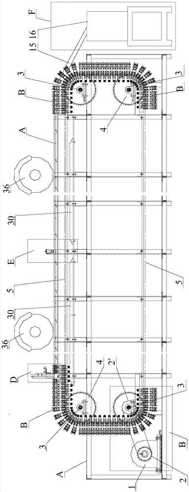
  • Figure 1
    Figure 1
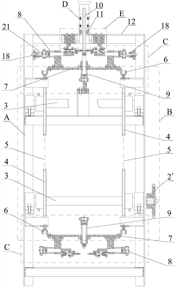
  • Figure 2
    Figure 2
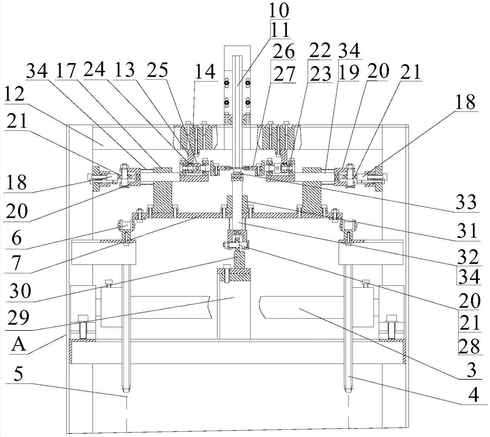
  • Figure 3
    Figure 3
Patent Text Reader

Abstract

The invention discloses an automatic polishing and feeding device for watch band grains. Power is transmitted to a driven sprocket by a driving motor mounted on a rack, a main drive sprocket and a drive chain, the driven sprocket drives a sprocket shaft to rotate so as to drive the drive chain to rotate, and thus a follow-up clamping mechanism is driven to run forwards; when the follow-up clamping mechanism runs to a feeding position, the watch band grains are automatically fed to a workpiece positioning block of a longitudinal clamping component from a feeding mechanism, and are clamped by a workpiece clamping block of a transverse clamping component, so that clamped conveyance of the watch band grains is implemented; while the watch band grains continue running forwards, upper surfaces of the watch band grains are polished by a left polishing wheel; when the follow-up clamping mechanism runs to a steering mechanism, the longitudinal clamping component retracts, the steering mechanism drives the watch band grains clamped by the transverse clamping component to rotate at an angle of 180 degrees, and then the longitudinal clamping component upwards supports workpieces; when the watch band grains continue moving forwards, the other surfaces of the watch band grains are polished by a right polishing wheel; and when forwards moving to a discharging mechanism, the watch band grains are discharged automatically, and automatic polishing of the watch band grains is finished.
Need to check novelty before this filing date? Find Prior Art

Description

technical field

[0001] The invention belongs to the technical field of mechanical equipment manufacturing, and relates to a polishing device, in particular to a feeding device suitable for automatic polishing of watch strap grains. Background technique

[0002] Due to the decoration requirements of existing watch strap parts, the outer surface of the strap grains usually needs to be polished, and the edges and corners must be kept sharp after polishing; Requirements, so it is difficult to achieve polishing by mechanical means. Therefore, most of the polishing of watch strap grains is carried out manually at present. The method is to put the watch band grains into the grooves of the mold one by one, and the workers hold the mold for polishing; and the disadvantages of manual polishing are: low production efficiency, The size of the watch strap grains is small, so it is necessary to put the watch band grains into the grooves of the mold for polishing one by one, which is very...

Examples

Embodiment Construction

[0028] The present invention will be described in detail below in conjunction with the accompanying drawings and specific embodiments.

[0029] A feeding device for automatic polishing of watch strap grains, such as Figure 1~2 As shown, the device consists of a frame A, a driving mechanism B installed on the frame A, a follow-up clamping mechanism C, a blanking mechanism D, a steering mechanism, and a blanking mechanism F.

[0030] The driving mechanism B of the present invention includes a drive motor 1 and a main transmission sprocket 2 installed at the bottom of the frame A, and the main transmission sprocket 2 is connected to two sprocket shafts 3 at both ends of the frame A via a driving chain via a driven sprocket. 2' driven, symmetrically installed transmission sprocket 4 and two transmission chains 5; on the inside of each pair of corresponding rollers 6 on the two transmission chains 5, one is connected by a bent plate to install the follower clamping mechanism C Th...