Multifunctional numerical-control spherical optical element milling and grinding tool

A technology of spherical optics and optical elements, applied in optical elements, optical surface grinders, optics, etc., can solve problems such as unfavorable small batch and multi-variety processing, and achieve the effect of improving processing efficiency and reducing the link of tooling adjustment

Inactive Publication Date: 2016-05-04
TIANJIN JINHANG INST OF TECH PHYSICS
View PDF9 Cites 9 Cited by
  • Summary
  • Abstract
  • Description
  • Claims
  • Application Information

AI Technical Summary

Problems solved by technology

Typical infrared optical components have at least one of the three characteristics of convex surface, concave surface, and platform in shape. Traditional tooling generally uses a certain feature as a positioning reference plane. Processing a component requires two to three kinds of tooling, which is not conducive to development. Small batch, multi-variety processing in the process

Method used


Image

  • Multifunctional numerical-control spherical optical element milling and grinding tool
  • Multifunctional numerical-control spherical optical element milling and grinding tool
  • Multifunctional numerical-control spherical optical element milling and grinding tool

Examples


Embodiment Construction

[0018] In order to make the purpose, content and advantages of the present invention clearer, the specific implementation manners of the present invention will be further described in detail below in conjunction with the accompanying drawings and embodiments.

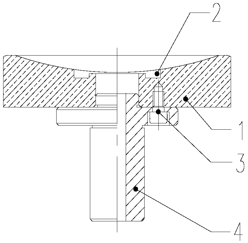
[0019] refer to figure 1 As shown, the multifunctional spherical optical element CNC milling tooling of this embodiment includes a fixture body 1, a water storage tank 2, a connecting screw 3 and a connecting head 4.

[0020] Fixture main body 1 is made of bakelite material, comprises body, the concave spherical surface formed on the upper part of the body, the annular platform formed on the periphery of the concave spherical surface, and the annular convex spherical surface formed on the periphery of the annular platform; the radius of the concave spherical surface is the same as that to be The radius of the convex surface of the processed optical element is the same, which is used to support the convex surface of the ...


PUM


Abstract

The invention discloses a multifunctional numerical-control spherical optical element milling and grinding tool. The multifunctional numerical-control spherical optical element milling and grinding tool comprises a clamp main body and a connector. The clamp main body comprises a body, an inward-concave spherical surface formed on the upper portion of the body, an annular platform formed on the periphery of the inward-concave spherical surface, and an outward-convex spherical surface formed on the periphery of the annular platform. The radius of the inward-concave spherical surface is consistent with that of a convex surface of an optical element to be machined, and the inward-concave spherical surface is used for supporting and placing the convex surface of the optical element to be machined. The width of the annular platform is not smaller than 4 mm, and the annular platform is used for supporting and placing a plane of the optical element to be machined. The radius of the outward-convex spherical surface is consistent with that of a concave surface of the optical element to be machined, and the outward-convex spherical surface is used for supporting and placing a concave surface of the optical element to be machined. The connector is connected with the bottom of the clamp main body in a matched mode and used for being connected with machine tool equipment for machining the optical element in a matched and positioned mode. According to the multifunctional numerical-control spherical optical element milling and grinding tool, through one tool clamp, the inner surface and the outer surface of the element can be machined, the number of tool adjustment links is reduced, and the machining efficiency is improved; the multifunctional numerical-control spherical optical element milling and grinding tool is suitable for small-batch and multi-variety machining in the development process.

Description

technical field [0001] The invention belongs to the technical field of optical element processing, and relates to a multifunctional spherical optical element numerical control milling tool, which is mainly used for numerical control milling or forming processing of optical elements. Background technique [0002] The CNC machining process of optical components is milling (forming) - polishing - centering and edging three processes. During the milling process, the shape of the part is initially formed, and its surface shape and shape and position accuracy are guaranteed. The tooling requirements for milling and grinding processing are relatively high, not only requiring accurate positioning of parts to meet the requirements of shape and position indicators, but also requiring convenient clamping and operation. Typical infrared optical components have at least one of the three characteristics of convex surface, concave surface, and platform in shape. Traditional tooling general...

Claims


Application Information

Patent Timeline
Patent Type & Authority Applications(China)
IPC IPC(8): B24B13/005B24B13/00
CPCB24B13/0055B24B13/00
Inventor 张昊王朋魏国梁
Owner TIANJIN JINHANG INST OF TECH PHYSICS
Why Eureka
Try Eureka