

Composite-wing vertical take-off and landing aircraft
A vertical take-off and landing, aircraft technology, applied in aircraft, rotorcraft, motor vehicles, etc., can solve the problems of poor yaw control ability, low structure utilization, etc., to improve robustness, avoid negative effects, and improve overall performance Effect
- Summary
- Abstract
- Description
- Claims
- Application Information
AI Technical Summary
Problems solved by technology
Method used
Image

Examples
Embodiment 1
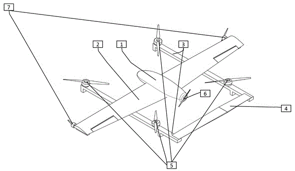
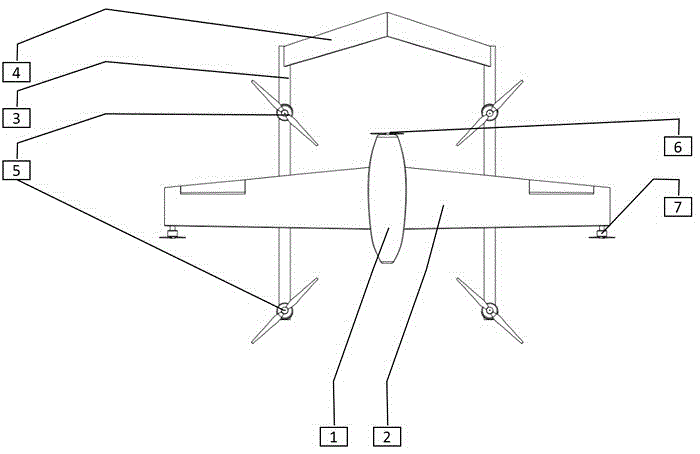
[0036] like Figure 1 to Figure 4 As shown, a compound wing vertical take-off and landing aircraft comprises a fuselage 1, a wing 2, a tail brace 3, an empennage 4, a vertical power unit 5 and a horizontal power unit 6, and the wing 2 is fixed on the middle section of the fuselage 1 , the wing 2 is symmetrical with respect to the longitudinal direction of the fuselage 1;
[0037] There are two tail braces 3, and different tail braces 3 are respectively fixed on the wings 2 on different sides of the fuselage 1;
[0038] The horizontal power unit 6 is fixed on the fuselage 1, and the left and right ends of the empennage 4 are respectively fixedly connected with the tails of different tail braces 3,
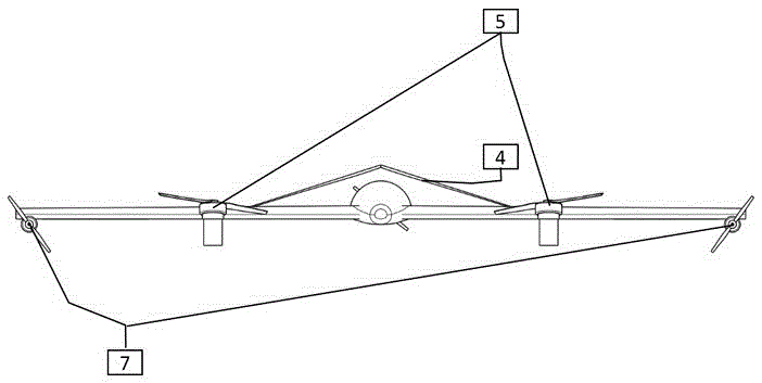
[0039] Described vertical power unit 5 is four, and each tail brace 3 is provided with two vertical power units 5, and the two vertical power units 5 on the same side of the fuselage 1 are located at different positions in the length direction of the aircraft, and the fuselage 1 A...
Embodiment 2
[0045] The present embodiment is further limited on the basis of embodiment 1, as Figure 1 to Figure 4 As shown, the rear edge of the empennage 4 is also hingedly connected with two aerodynamic rudder surfaces that are in a left-right symmetrical relationship with each other. The aerodynamic rudder surface is an elevating rudder, so that the flight attitude of the aircraft can be adjusted through the aerodynamic rudder surface when the aircraft is flying in a fixed-wing attitude.
[0046] The wings 2 on both sides of the fuselage 1 are provided with a yaw control unit 7, the yaw control unit 7 includes a yaw propeller, and the yaw propeller is used to provide the wing 2 with a direction parallel to the length of the fuselage 1. direction, and the yaw control unit 7 is close to the end of the wing 2 .
[0047] In the above scheme, the yaw control unit 7 is used to provide the yaw moment, and the mechanism is as follows: the left and right yaw control units 7 of the aircraft a...
Embodiment 3
[0054] This embodiment is further limited on the basis of any one of the technical solutions provided by the above embodiments, such as Figure 1 to Figure 4 , in order to change the wing 2 output yaw moment and roll moment through the wing 2 under the high-speed flight state of the aircraft, and facilitate the adjustment of the above-mentioned yaw moment and roll moment at the same time, the wings 2 on each side of the fuselage 1 A piece of aileron is hingedly connected on the top, and the two ailerons are symmetrical with respect to the length direction of the fuselage 1. The inclination angle of the aileron and the wing 2, and the inclination angle of the aileron and the fuselage 1 are all adjustable.
[0055] As a specific implementation form of the drive device for braking the rotation of the level-flying propeller, the level-flying propeller is driven by an internal combustion engine or an electric motor. It is preferably set that the driving device includes an internal ...
PUM
 Abstract
Description
Claims
Application Information