A Winding Method for Coils of Layer Type Distribution Transformer Coils Radiating to Multiple Parallel Windings

A technology of distribution transformer and winding method, which is applied in inductance/transformer/magnet manufacturing, circuits, electrical components, etc., can solve the problems of multi-use copper, increase silicon steel sheets, etc., achieve small vacancies, reduce coil height, and reduce volume Effect

Inactive Publication Date: 2017-03-29
武汉振源电气股份有限公司
View PDF3 Cites 0 Cited by
  • Summary
  • Abstract
  • Description
  • Claims
  • Application Information

AI Technical Summary

Problems solved by technology

[0002] Most of the low-voltage windings of distribution transformers adopt a layered structure. Due to the large current, multiple wires need to be wound in parallel. Transposition (to reduce the circulation loss between the winding wires), but the height of the wire needs to be increased by 1 turn for transposition, which not only requires more copper, but also increases the weight of the silicon steel sheet, fuel tank and oil due to the increase in the height and size of the iron core

Method used


Image

  • A Winding Method for Coils of Layer Type Distribution Transformer Coils Radiating to Multiple Parallel Windings
  • A Winding Method for Coils of Layer Type Distribution Transformer Coils Radiating to Multiple Parallel Windings
  • A Winding Method for Coils of Layer Type Distribution Transformer Coils Radiating to Multiple Parallel Windings

Examples


Embodiment Construction

[0021] The present invention will be described in detail below in conjunction with the accompanying drawings and embodiments, and the content of the present invention is not limited to the following embodiments.

[0022] The method for winding radially multi-layered distribution transformer coils wound side by side in the present invention comprises the following steps:

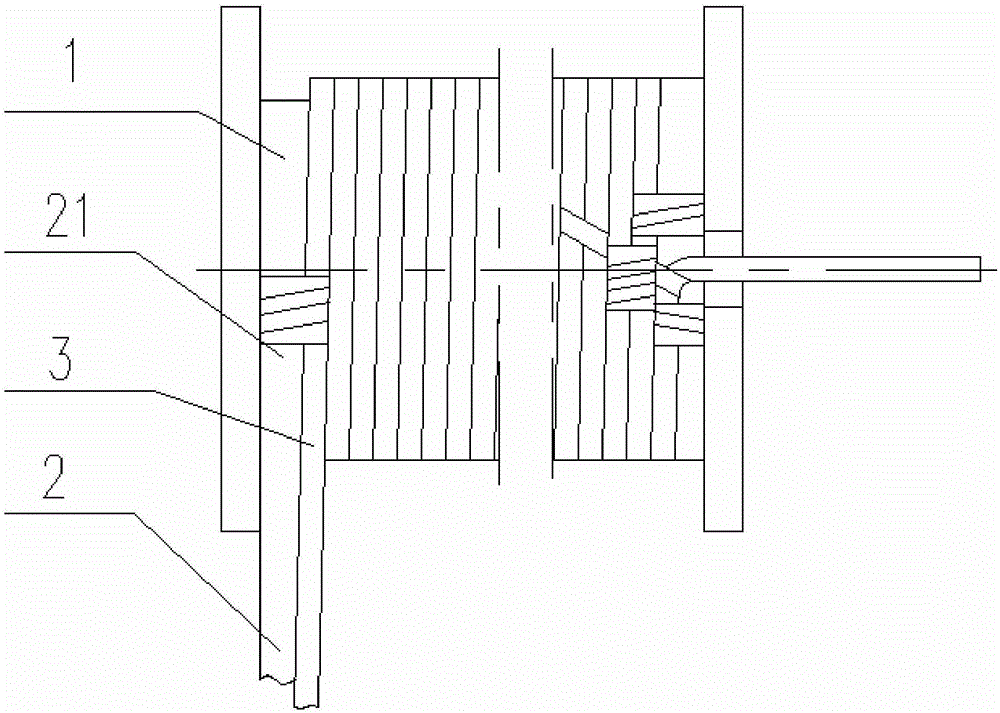
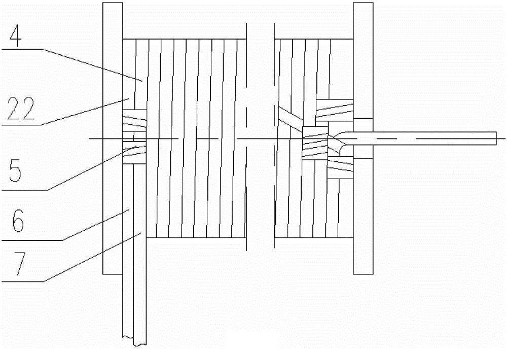
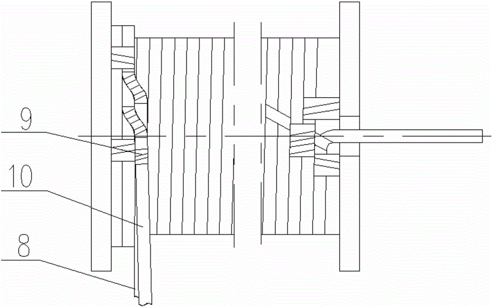
[0023] (1) Wind the first layer of coils from the beginning to the end on the winding mold 1, bind the wedge-shaped end insulation 2 whose height difference between the big end and the small end is the height of one turn of the coil at the beginning of the penultimate turn 3 of the first layer, and wrap the wedge-shaped The big end 21 of the end insulation is bound and fixed to the beginning of the penultimate turn of the first layer, and then the wire and the wedge-shaped end are insulated and wound side by side to complete the last turn 4 of the first layer, such as figure 1 with figure 2 shown;

[0024]...


PUM


Abstract

The invention provides a winding method for multiple radial parallel winding layer distribution transformer coils. A first layer of coil is wound on a winding mold, the start end of the second last turn of the first layer is bound with a wedge-shaped end insulator, and then the last turn of the first layer is completed through parallel winding; after the coil is lifted, the coil is bound with a parallel end insulator, interlayer insulation paper is laid, and then the first turn of the second layer is completed through parallel winding; transposition is carried out on the tail of the first turn of the second layer, the start end of the second turn of the second layer is bound with a beveled jointing paperboard strip after completing transposition, a spiral line wound at the second layer is formed, and the second turn of the second layer is completed through parallel winding of a lead and the beveled jointing paperboard strip; and the lead is wound with the rest of the second layer along the spiral line. According to the winding method, two layers of coils are taken as one unit, the coil transposition is carried out on the tail of the first turn of the second layer, the height of the coil formed by winding is one turn height smaller than the height of the coil formed by middle transposition winding, 3% of the total cost of the distribution transformer is reduced and the volume of the distribution transformer is decreased.

Description

technical field [0001] The invention provides a winding method of multi-layer parallel distribution transformer coils, which belongs to the technical field of distribution transformers. Background technique [0002] Most of the low-voltage windings of distribution transformers adopt a layered structure. Due to the large current, multiple wires need to be wound in parallel. Transposition (to reduce the circulation loss between the winding wires), but the transposition needs to increase the height of one turn of the wire, not only requires more copper, but also increases the weight of the silicon steel sheet, fuel tank and oil due to the increase in the height and size of the iron core. Contents of the invention [0003] The purpose of the present invention is to overcome the deficiencies of the prior art and provide a winding method for multi-layered distribution transformer coils that are radially wound side by side, which can reduce the height of the coils and reduce the ...

Claims


Application Information

Patent Timeline
Patent Type & Authority Patents(China)
IPC IPC(8): H01F41/069H01F41/071
Inventor 欧立新
Owner 武汉振源电气股份有限公司
Why Eureka
Try Eureka