An intensified concentrated swirl pulverized coal burner

A pulverized coal burner, a concentrated type technology, which is applied to burners, burners for burning powder fuel, combustion methods, etc. Effects of NOx emission and NOx generation suppression

Inactive Publication Date: 2017-11-03
ZHENGZHOU UNIVERSITY OF LIGHT INDUSTRY +1
View PDF5 Cites 7 Cited by
  • Summary
  • Abstract
  • Description
  • Claims
  • Application Information

AI Technical Summary

Problems solved by technology

The first two measures are easy to cause the pulverized coal to be separated to the inner wall area of ​​the primary air channel, which will cause the pulverized coal of the primary air to mix with the swirling secondary air prematurely, which is not conducive to the control of NO X The third measure is to set up "the secondary air structure of the burner arranged in steps, so that the rotating internal and external secondary air can inject the primary air step by step" will cause two problems: (1) the primary air powder is burning The nozzle of the burner is prematurely mixed with the secondary air, or the primary air powder is ejected to the secondary air area by the secondary air, which weakens the graded combustion effect of the thick and thin fuel; (2) The structure of the secondary air nozzle of the burner arranged in steps makes the The secondary air participates in pulverized coal combustion prematurely, which weakens the effect of air staged combustion
Both of these problems are not conducive to the inhibition of NO x generated, limiting the swirl burner NO x removal ability
Therefore, the current three methods limit the swirl burner to further reduce NO x discharge capacity

Method used


Image

  • An intensified concentrated swirl pulverized coal burner
  • An intensified concentrated swirl pulverized coal burner
  • An intensified concentrated swirl pulverized coal burner

Examples


specific Embodiment 1

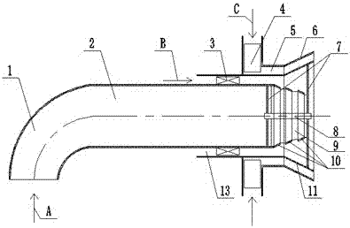
[0024] Such as figure 1 As shown, the present invention includes a primary air channel 2, an inner secondary air channel 13, and an outer secondary air channel 5 arranged coaxially from the inside to the outside, and an inner secondary air cyclone is arranged in the inner secondary air channel 13 3. An external secondary air cyclone 4 is provided in the external secondary air channel 5, the internal secondary air cyclone 3 and the external secondary air cyclone 4, one of which is a tangential cyclone, and the other One is an axial swirler; a primary air nozzle is provided at the outlet end of the primary air channel 2, an inner secondary air nozzle 11 is provided at the outlet end of the inner secondary air channel 13, and an inner secondary air nozzle 11 is provided at the outlet end of the outer secondary air channel 5. An outer secondary air nozzle 6 is provided, and the inner secondary air nozzle 11 and the outer secondary air nozzle 6 are conically flared, and the inner d...

specific Embodiment 2

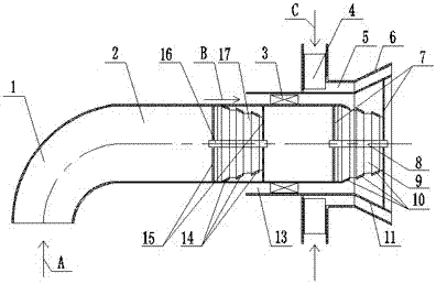
[0026] Such as image 3 As shown, in the primary air channel 2 of the swirl pulverized coal burner described in the specific embodiment 1, a conical pulverized coal concentrator is coaxially arranged, and the conical pulverized coal concentrator includes a second central axis 16, the The two ends of the second central axis 16 are respectively fixed on the inner wall of the primary air passage 2 through a plurality of fixing steel bars 15, and a plurality of second support plates 17 are evenly arranged around the circumferential direction of the second central axis 16, and along the second central axis 16 The axial direction is the length direction of the second support plate 17, the radial direction along the second central axis 16 is the height direction of the second support plate 17, the outer edge of the second support plate 17 is to the second central axis 16 The distance is the height of the second support plate 17, the distance from the outer edge of the second support ...

specific Embodiment 3

[0027] Such as Figure 4 As shown, in the primary air channel 2 of the swirl pulverized coal burner described in the specific embodiment 2, a concentrated pulverized coal airflow separation pipe 18 is coaxially arranged, and the concentrated pulverized coal airflow separation pipe 18 is located in the conical pulverized coal concentrator Between the primary air nozzle, the inner diameter of the dense pulverized coal air separation pipe 18 is equal to the minimum inner diameter of one or more stages of conical rings 14; further, one end of the dense pulverized coal air separation pipe 18 can also be connected to Shaped pulverized coal concentrator is connected, the other end of thick coal pulverized air flow separation pipe 18 is provided with interval between the primary air spout. The setting of the dense pulverized coal air flow separation pipe 18 can make the pulverized coal air flow passing through the conical pulverized coal concentrator continue to run forward to the pri...


PUM


Abstract

The invention discloses a reinforcement and concentration type cyclone pulverized coal burner. The cyclone pulverized coal burner comprises a primary wind channel, an inner secondary wind channel and an outer secondary wind channel coaxially arranged in sequence from inside to outside; a primary wind nozzle is formed in an outlet end of the primary wind channel; an inner secondary wind nozzle is formed in an outlet end of the inner secondary wind channel; an outer secondary wind nozzle is formed in an outlet end of the outer secondary wind channel; the inner secondary wind nozzle and the outer secondary wind nozzle are both conically expanded; the inner diameters of the inner secondary wind nozzle and the outer secondary wind nozzle are gradually increased in a primary wind airflow direction; and the inner secondary wind nozzle is positioned in the outer secondary wind nozzle. The cyclone pulverized coal burner solves the problem of primary wind pulverized coals dispersed to a secondary wind flowing area, realizes the concentration classified combustion of the pulverized coals, solves the problem of too early mixing of a secondary wind and primary wind-powder mixture, realizes the air classification combustion, and achieves the purpose of reducing the generation of NOX.

Description

technical field [0001] The invention belongs to the technical field of combustion, in particular to an intensified and concentrated swirl pulverized coal burner. Background technique [0002] During the period from 1995 to 2000, the national NO X The total emission increased from 10.9 million tons to 12 million tons, an increase of only 1.1 million tons. However, it increased sharply to 24.0427 million tons in 2011, due to NO X It is one of the main precursors for the formation of haze weather and acid rain. The number of haze weather in my country is increasing and the duration is getting longer and longer. This not only affects traffic and crop growth, but also endangers human health, such as inducing heart disease, bronchial disease and lung cancer. Therefore, controlling NO X Emissions have become a top priority for environmental protection. According to statistics, more than 60% of NO X Emissions come from burning coal, about 55% of China's total coal consumption i...

Claims


Application Information

Patent Timeline
Patent Type & Authority Patents(China)
IPC IPC(8): F23D1/02
CPCF23D1/02
Inventor 遆曙光宋寅卯胡张保张文慧牛聪闫丽云李春艳聂雪丽王振锋况敏
Owner ZHENGZHOU UNIVERSITY OF LIGHT INDUSTRY
Why Eureka
Try Eureka