Bar device for warp knitting machine

A warp knitting machine and bar technology, which is applied in the field of bar devices, can solve the problems of non-constant tension and change in tension.

Inactive Publication Date: 2018-05-22
KARL MAYER R&D GMBH
View PDF7 Cites 0 Cited by
  • Summary
  • Abstract
  • Description
  • Claims
  • Application Information

AI Technical Summary

Problems solved by technology

However, it is problematic that the pulling force is not constant for the bar arrangement disclosed in DE 100 35 160 A1, since pressure changes of the pressure medium occur when the piston moves in the cylinder, so The change in pressure in turn leads to a change in force

Method used


Image

  • Bar device for warp knitting machine
  • Bar device for warp knitting machine
  • Bar device for warp knitting machine

Examples


Embodiment Construction

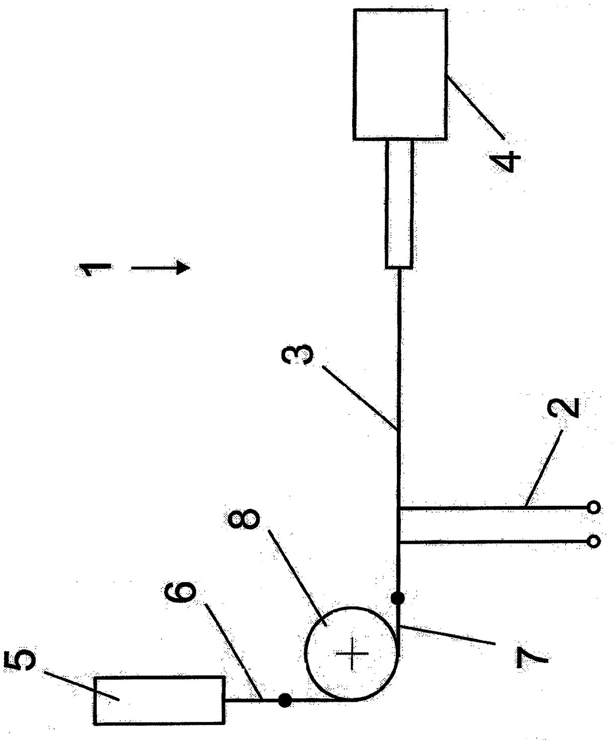
[0025] exist figure 1 The bar device 1 for a warp knitting machine shown schematically in , has a plurality of thread guides 2 which are arranged on a drive element 3 . In the present exemplary embodiment, drive element 3 is designed as a thin wire or as a cable. The drive element 3 is therefore not rigid and therefore cannot be loaded with pressure.

[0026] The drive element 3 is connected at one end to a drive mechanism 4 . The drive 4 can be designed, for example, as a jacquard drive. It can also have a linear drive.

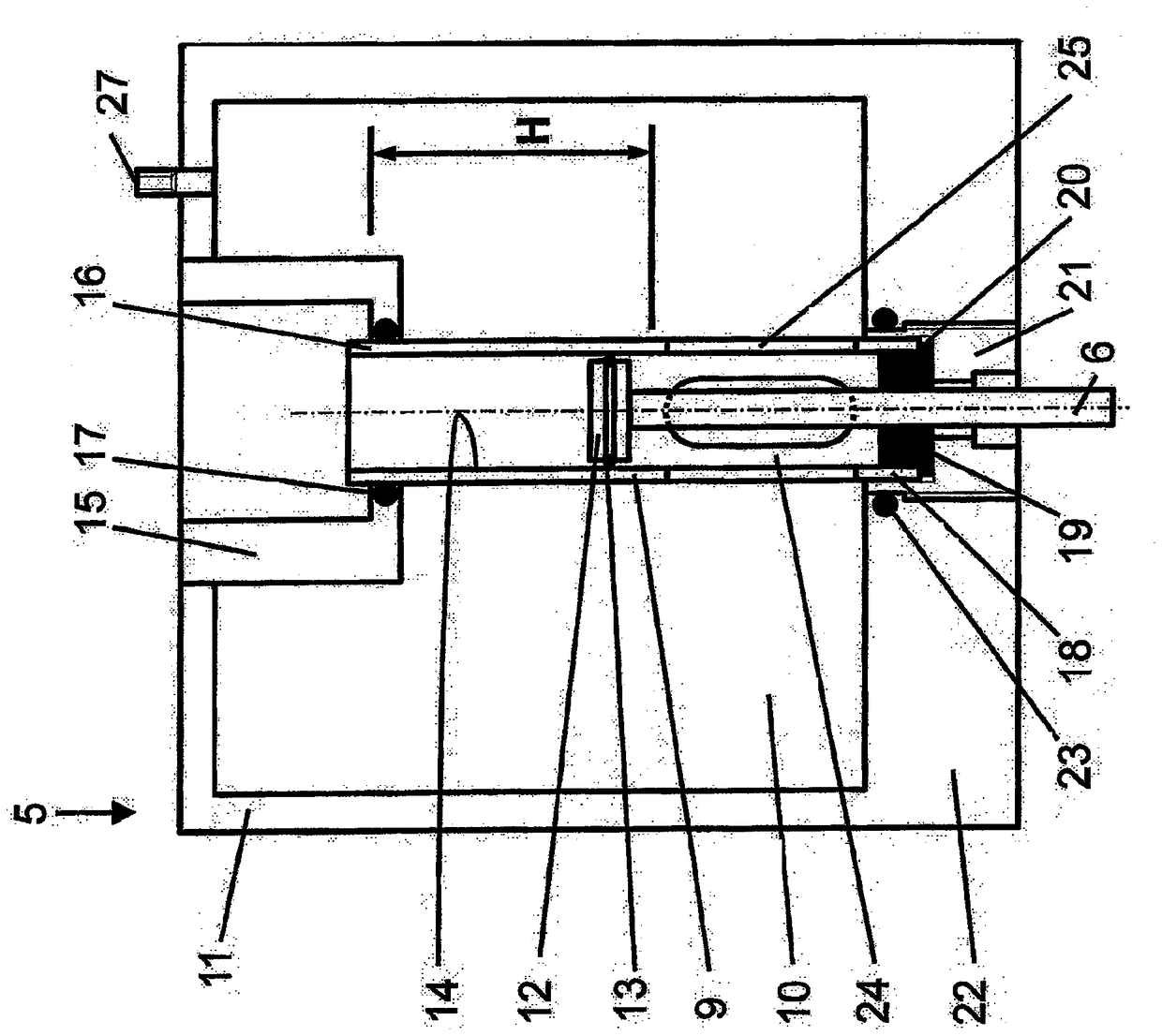
[0027] At the other end, the drive element 3 is connected to a counterforce element 5 . combine figure 2 The reaction force element 5 will be described in detail. The counterforce element 5 has a piston rod 6 which is connected to the drive element 3 via an intermediate element 7 . The intermediate element 7 is guided by deflection rollers 8 . It is also possible to connect the drive element 3 directly to the piston rod 6 .

[0028] The counterforc...


PUM


Abstract

The invention relates to a lay bar of a warp knitting machine which has at least a guide bar device arranged on a driving element. The driving element and a driving mechanism as well as at least a counter force element (5) are arranged in connection, wherein the counter force element (5) has a piston-cylinder-device. For the piston-cylinder-device, a piston connected to the driving element through a piston rod (6) can move in a cylinder (9) with a certain cylinder cross section in a stroke length (H) region and can be loaded through a pressure medium. People intend to keep the stress change in the driving element little. Therefore the cylinder (9) is arranged in a cavity (10) of a vessel (11) filled by the pressure medium. The cavity (10) has the capacity larger than the external capacity of the cylinder (9) and is in connection with an internal space of the cylinder (9) on a side surface of the piston (12) provided with a piston rod (6). The cylinder (9) is connected to the vessel (11) at at least two positions in a direction parallel to the stroke length (H). The two positions have an interval.

Description

technical field [0001] The invention relates to a bar arrangement of a warp knitting machine, which has at least one thread guide which is arranged on a drive element which is in operative connection with a drive mechanism and with at least one counterforce element wherein the reaction force element has a piston-cylinder arrangement for which a piston connected to the drive element via a piston rod can travel the length of the stroke in a cylinder with a cylinder cross-section (Hublänge) and can be loaded by pressure medium. Background technique [0002] Such a bar arrangement is known, for example, from DE 100 35 160 A1. The drive mechanism moves the drive element and thus the yarn guide connected to the drive element, so that the yarn guided by the yarn guide can be woven into the knitting machine according to a predetermined pattern. in the product. If the drive element is designed to be non-rigid - as is the case for so-called "string barres" - the drive mechanism and...

Claims


Application Information

Patent Timeline
Patent Type & Authority Patents(China)
IPC IPC(8): D04B27/26F15B15/14F15B15/20
CPCD04B27/26F15B15/1423F15B15/1461D04B27/24D04B27/32
Inventor A.凯勒
Owner KARL MAYER R&D GMBH
Why Eureka
Try Eureka