Electromagnetically actuatable spring pressure brake and method for the production thereof

A spring pressure, brake technology, applied in the direction of brake type, automatic brake, brake components, etc., can solve the problems of large air gap, increase installation cost, and tolerance is not eliminated, and achieve the effect of small air gap

Active Publication Date: 2016-08-24
KENDRION VILLINGEN GMBH
View PDF6 Cites 12 Cited by
  • Summary
  • Abstract
  • Description
  • Claims
  • Application Information

AI Technical Summary

Problems solved by technology

[0007] As a disadvantage, it can be considered that the production-dependent component tolerances of friction disk and armature are not eliminated for the known method, and in the worst case the air gap results in a resultant change due to these tolerances (addition). bigger
In addition, the insertion and removal of the distance elements takes a lot of time and thus increases the installation costs

Method used


Image

  • Electromagnetically actuatable spring pressure brake and method for the production thereof
  • Electromagnetically actuatable spring pressure brake and method for the production thereof
  • Electromagnetically actuatable spring pressure brake and method for the production thereof

Examples


Embodiment Construction

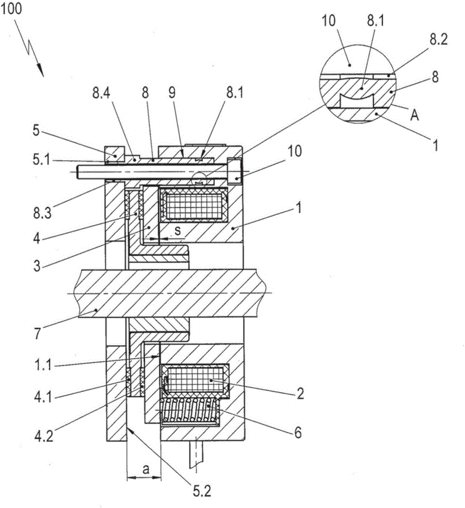
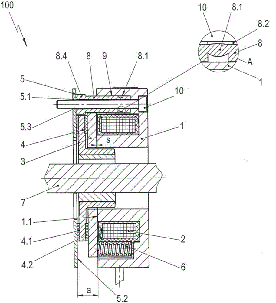
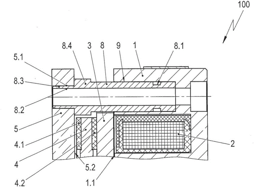
[0065] according to Figure 1-a The electromagnetically operable spring pressure brake 100 comprises a pot-shaped magnet as a magnet housing 1, the pot-shaped magnet has a for example annular coil 2 housed in the pot-shaped magnet 1, and the electromagnetically operable spring pressure brake 100 For example, it is arranged concentrically with respect to the shaft 7 to be braked, for example the motor shaft. Arranged in a rotationally fixed manner on the shaft 7 to be braked is a friction disk 4 which is situated between the armature 3 and the friction plate 5 as a friction element with a friction surface 5.2, the armature 3 being radially guided, However, it is axially displaceable and the friction plate 5 is connected to the magnet housing 1 by means of a plurality of screw-shaped connecting elements 8 . The friction surface 5 . 2 is located on the side of the friction plate 5 which is adjacent to the friction disk 4 . exist Figure 1-a Only a single screw-shaped connecting ...


PUM


Abstract

The invention relates to an electromagnetically actuatable spring pressure brake (100), comprising: a magnet housing (1) having a coil (2); an armature (3), which is arranged coaxial to the coil (2) and in such a way that the armature can be moved axially with respect to a shaft (7) to be braked; a friction element (5), which is spaced in a rotationally fixed manner with respect to the magnet housing (1) by means of at least one bolt-shaped connecting element (8) and which has a friction surface (5.1); a friction disk (4), which is arranged between the armature (3) and the friction element (5) and which is arranged in a rotationally fixed manner on the shaft (7) to be braked; and at least one compression spring (6), which applies pressure to the armature (3) and the spring force of which causes a braking torque on the shaft (7) to be braked in the currentless state of the coil (2) by the pressing of the friction disk (4) against the armature (3) and against the friction surface (5.1) of the friction element (5). According to the invention, for the adjustment of the distance (a) between the friction element (5) and the magnet housing (1), the at least one bolt-shaped connecting element (8) is designed having a compression zone (8.1) that can be compressed in an axial direction of the connecting element. According to alternative solutions, the compression zone can also be arranged in the region of a blind hole (9) accommodating the at least one connecting element (8) or in an accommodating opening (5.1) of a brake element (5) designed as a brake plate. The invention further relates to a method for producing the spring pressure brake (100) according to the invention.

Description

technical field [0001] The invention relates to an electromagnetically actuatable spring pressure brake according to the preamble of claim 1 and according to the preamble of claim 5 as well as a method for producing a spring pressure brake according to the invention. Background technique [0002] DE 2832723 A1 discloses an electromagnetically actuable spring pressure brake of the same family. For such a spring pressure brake, there is an air gap between the pole faces of the magnet housing with the coil and the armature, which is fixed against rotation with the friction disc arranged on the shaft to be braked and with the magnet housing Together with the friction plates connected by means of screw-shaped connecting elements, a braking torque is generated on the shaft to be braked. For this purpose, compression springs are arranged in the magnet housing, which press the armature in the direction of the brake plate when the coil is not energized, whereby the braking torque is...

Claims


Application Information

Patent Timeline
Patent Type & Authority Applications(China)
IPC IPC(8): F16D65/18F16D65/54F16D59/02F16D121/14F16D121/22
CPCF16D59/02F16D65/186F16D65/543F16D2121/14F16D2121/22
Inventor 沃尔德马·谢尔曼尤韦·纳尤特
Owner KENDRION VILLINGEN GMBH
Why Eureka
Try Eureka