

Drying device
A drying device and drying chamber technology, applied in spray evaporation, evaporator accessories, evaporation, etc., can solve problems such as wall sticking, difficulty in spray drying process, and difficulty in dispersing moisture
- Summary
- Abstract
- Description
- Claims
- Application Information
AI Technical Summary
Problems solved by technology
Method used
Image

Examples
Embodiment Construction
[0017] The present invention is described in further detail now in conjunction with accompanying drawing. These drawings are all simplified schematic diagrams, which only illustrate the basic structure of the present invention in a schematic manner, so they only show the configurations related to the present invention.
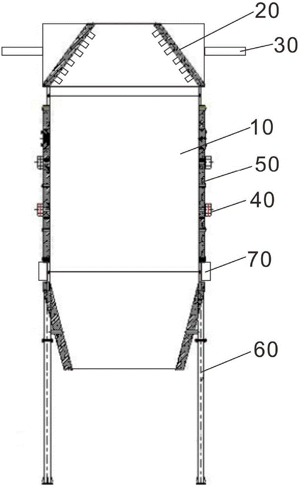
[0018] Such as figure 1 as shown, figure 1 It is a structural schematic diagram of a preferred embodiment of the drying device of the present invention.
[0019] The present invention provides a drying device, which includes a drying chamber 10, a gas injection plate 20, an air inlet pipe 30, a frame 60 and a vibrator 40. The drying chamber 10 has a cylindrical structure, and its upper end is provided with a pre-set angle and a The airflow injection plate 20 connected to the air pipe 30 is preferably a cone-shaped structure, which has several air guide pipes for spraying dry gas into the drying chamber 10 to blow off the attachments on the inner wall of the ...
PUM
 Abstract
Description
Claims
Application Information