Design method of distributed antenna wireless energy transmission network architecture

A wireless energy transmission and distributed antenna technology, applied in electrical components, circuit devices, etc., can solve the problem that the signal received power is greatly affected by large-scale attenuation, and achieves increased efficiency of long-distance wireless energy transmission, simple implementation, and improved efficiency. Effect

Inactive Publication Date: 2016-11-09
XI AN JIAOTONG UNIV
View PDF2 Cites 2 Cited by
  • Summary
  • Abstract
  • Description
  • Claims
  • Application Information

AI Technical Summary

Problems solved by technology

[0004] The purpose of the present invention is to provide a distributed antenna wireless energy transmission network architecture design method to overcom

Method used


Image

  • Design method of distributed antenna wireless energy transmission network architecture
  • Design method of distributed antenna wireless energy transmission network architecture
  • Design method of distributed antenna wireless energy transmission network architecture

Examples


Embodiment Construction

[0055] The present invention will be further described below in conjunction with the accompanying drawings and specific embodiments.
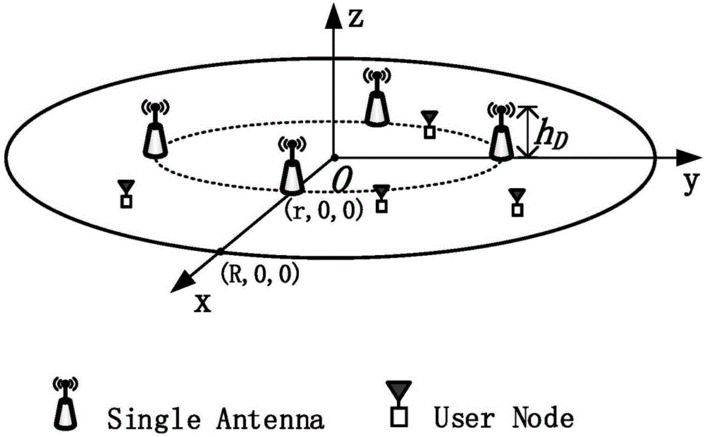
[0056] Suppose the coverage area of ​​Power Beacon is as follows figure 1 As shown in the disc cell, the center of the cell is O, and the radius is R. What the present invention considers is a uniform circular layout distributed antenna array, and Power Beacon has N distributed antennas (for the convenience of illustration, figure 1 where N=4), and these distributed antennas are evenly distributed on concentric circles with a radius of r, and all antennas are distributed with equal power, and all are omnidirectional antennas. The Power Beacon central processor is located at O ​​(for simplicity, not shown in the figure), the central processor is connected to the grid or has continuous energy supplementation, and is mainly responsible for delivering power to the distributed antenna. All N distributed antennas are connected to the central proces...


PUM


Abstract

The invention discloses a design method of a distributed antenna wireless energy transmission network architecture, specifically, the distributed antenna wireless energy transmission network architecture. A rounded covering residential area is taken into account, and uniform circular antenna layout is also taken into account. When a power beacon (PB) distributed antenna is used, a closed expression of averagely collected direct-current power of users in the residential area and average wireless energy transmission efficiency of the PB distributed antenna is solved; the electromagnetic radiation requirement of FCC is taken into account, and a closed expression of the minimum antenna height of the distributed antenna when the residential area is free of a radiation forbidden zone is firstly solved; and secondly, in order to maximize the average wireless energy transmission efficiency of the distributed antenna, a closed expression of optimal distributed antenna concentric circle radius is solved and obtained. Experimental results show that the average transmission efficiency of wireless energy transmission is obviously improved compared with the performance of an integrated antenna by using the distributed antenna wireless energy transmission architecture disclosed by the invention.

Description

Technical field: [0001] The invention belongs to the technical field of radio frequency wireless energy transmission, and in particular relates to a method for designing a distributed antenna wireless energy transmission network architecture. Background technique: [0002] Traditional wireless networks (such as wireless sensor networks) have limited node energy, which limits the life of the network and greatly affects the performance of the network, especially for Q O S (Quality of Service) has a demanding network, and the impact is more prominent. The long-distance wireless energy transmission can charge the nodes in the network wirelessly, thereby prolonging the service life of the network nodes. In addition, in the sensor network, some energy-constrained network nodes are embedded in walls, some are inside the human body, and some are in remote areas or in toxic environments. If artificially "charging" or "changing batteries , costly, inconvenient and sometimes dangerou...

Claims


Application Information

Patent Timeline
IPC IPC(8): H02J50/20H02J50/23H02J50/90
Inventor 张超赵广河
Owner XI AN JIAOTONG UNIV
Why Eureka
Try Eureka