A led dimming circuit

A dimming circuit, LED array technology, applied in the direction of light source, electric light source, electrical components, etc., can solve the problems of poor continuity and linearity of adjustment, intelligent adjustment of high-frequency flicker, inconvenient application software, etc., so that there is no high Frequent flashing, convenient intelligent adjustment and control, continuous current effect

Active Publication Date: 2017-10-03
XIAMEN INTERACTIVE TECH
View PDF13 Cites 0 Cited by
  • Summary
  • Abstract
  • Description
  • Claims
  • Application Information

AI Technical Summary

Problems solved by technology

In short, the existing LED drive circuits have shortcomings such as inability to adjust light, poor continuity and linearity of adjustment, inconvenient combination of intelligent adjustment with application software, and high-frequency flicker.

Method used


Image

  • A led dimming circuit
  • A led dimming circuit
  • A led dimming circuit

Examples


Embodiment Construction

[0032] The following will clearly and completely describe the technical solutions in the embodiments of the present invention in conjunction with the accompanying drawings in the embodiments of the present invention. Obviously, the described embodiments are only preferred embodiments of the present invention, not all embodiments. Based on the embodiments of the present invention, all other embodiments obtained by persons of ordinary skill in the art without creative efforts fall within the protection scope of the present invention.

[0033] The circuits, working methods and beneficial effects of the present invention will be described in detail below in conjunction with the drawings and embodiments.

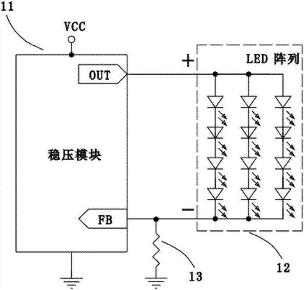
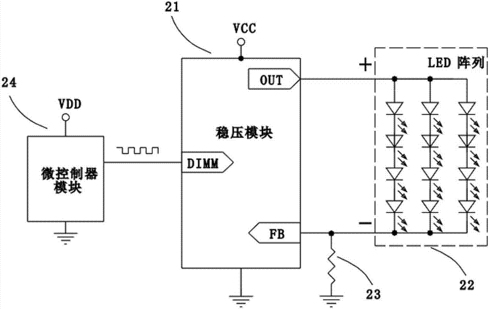
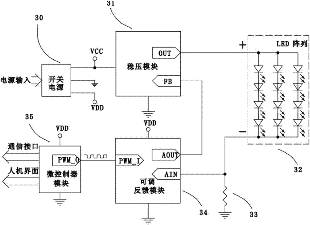
[0034] Please refer to the attached image 3 , an LED dimming circuit, including a switching power supply 30, a voltage stabilizing module 31, an LED array 32, a sampling resistor 33, an adjustable feedback module 34 and a microcontroller module 35.

[0035] The input of the abo...


PUM


Abstract

The invention discloses an LED dimming circuit, which comprises a switching power supply, a voltage stabilizing module, an LED array, a sampling resistor, an adjustable feedback module and a microcontroller module. The voltage regulator module is connected to provide power and zero potential "ground"; the power output port of the voltage regulator module is connected to the positive interface of the LED array; the feedback input port of the voltage regulator module is connected to the voltage output port of the adjustable feedback module; the adjustable feedback module The voltage input port of the LED array is connected to the negative interface of the LED array, and is connected to one end of the sampling resistor at the same time; the other end of the sampling resistor is connected to the zero potential "ground"; the pulse input port of the adjustable feedback module is connected to the pulse output of the microcontroller module port connection. The invention can continuously adjust the brightness, has good linearity, no high-frequency flicker, and is convenient for intelligent adjustment and control in combination with various application software.

Description

technical field [0001] The invention relates to the field of smart home and LED lighting, in particular to an LED dimming circuit. Background technique [0002] LED lights have the advantages of energy saving and environmental protection, long life, small size, flexible control, etc., and are more and more widely used in the field of lighting. In some occasions, the brightness of the LED needs to be adjusted, and in many cases, it needs to be intelligently adjusted in conjunction with the application software, instead of manually adjusting the knob or other physical switches on the lamp. [0003] For a given LED, its luminous brightness depends on the current flowing through it. [0004] Reference attached figure 1 As shown, an existing LED constant current driving circuit mainly includes a switching power supply (not shown in the figure), a voltage stabilizing module 11 , an LED array 12 and a sampling resistor 13 . The switching power supply is input into commercial pow...

Claims


Application Information

Patent Timeline
Patent Type & Authority Patents(China)
IPC IPC(8): H05B33/08H05B44/00H05B45/10H05B45/30H05B45/325H05B45/34
CPCH05B45/00H05B45/10
Inventor 孙国郑彦斌吴奎彬
Owner XIAMEN INTERACTIVE TECH
Why Eureka
Try Eureka