Active camera system for measuring projectile flight state and its measurement method

A technology of flight status and camera system, applied in the direction of ammunition testing, ammunition, offensive equipment, etc., can solve problems such as inability to meet, such as large amount of blur, long duration of light source flash, etc., to reduce losses and reduce energy requirements. , Improve the effect of shooting

Inactive Publication Date: 2018-11-16
XIAN TECH UNIV
View PDF6 Cites 2 Cited by
  • Summary
  • Abstract
  • Description
  • Claims
  • Application Information

AI Technical Summary

Problems solved by technology

In the spark flash shadow photography system commonly used in the past, because the spark light source is used to provide the light source for the imaging of the camera, only one flash projectile image can be captured each time, and the light source flash lasts for a long time, resulting in a large amount of image blur, which has been Unable to meet people's requirements for higher precision measurement
In recent years, with the rapid development of laser technology, lasers have been widely used as light sources. In the field of photogrammetry technology, lasers are combined with high-speed CCD cameras, and laser flashes are fast and high-speed CCD cameras have high resolution and fast response. and other advantages, a digital target shadow photography system was designed, but the system can only realize a pair of shadow images at different positions on an image, and the field of view of the camera is limited by the laser light source, and the requirements for laser energy are also low. relatively high

Method used


Image

  • Active camera system for measuring projectile flight state and its measurement method
  • Active camera system for measuring projectile flight state and its measurement method
  • Active camera system for measuring projectile flight state and its measurement method

Examples


Embodiment Construction

[0017] In order to make the objectives, technical solutions and advantages of the present invention clearer, the present invention will be further described in detail below with reference to the accompanying drawings and embodiments. It should be understood that the specific embodiments described herein are only used to explain the present invention, but not to limit the present invention.

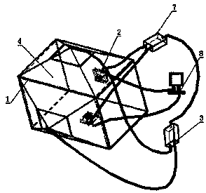
[0018] see figure 1 : This embodiment provides an active camera system for measuring the flight state of a projectile, including a rectangular outer structure frame 1, a laser 3, a timing controller 7 of an FPGA, and a host computer 8, and the outer structure frame 1 is closed around. The frame body of the outer structure frame is respectively provided with a background light source surface 4 on two adjacent vertical surfaces of the outer structure frame, and a panel is respectively provided on the other two adjacent surfaces;

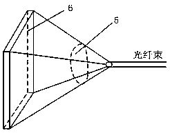
[0019] see figure 2 : The background light source surface ...


PUM


Abstract

The invention discloses an active camera system for measuring the flying state of a projectile and a measuring method thereof. The camera system is composed of a laser, a high-speed CCD (Charge Coupled Device) camera, an outer structural frame, a time schedule controller of a FPGA (Field Programmable Gate Array) and an upper computer, wherein laser emitted by the laser is divided into two parts as background light sources, the laser light sources and the high-speed CCD camera are controlled by the time schedule controller of the FPGA, when the laser emits laser, the CCD camera begins to shoot and keeps for certain exposure time, the laser light sources flicker for many times, so that positions of a target in different time can be obtained in the same photo, and the photo is transmitted to the upper computer by the CCD camera through a network cable after shooting is finished. According to the active camera system, the field requirement of the camera can be satisfied to the maximum, and while a clear target image is obtained, the energy requirement of the laser light sources is reduced.

Description

technical field [0001] The invention belongs to the technical field of projectile flight state testing and measurement, and relates to an active camera system for measuring the projectile flight state and a measurement method thereof. Background technique [0002] Photogrammetry technology is an important non-contact test method for the performance and flight attitude of high-speed or ultra-high-speed moving targets. It plays a very important role in the test and measurement of conventional ordnance weapons in my country. In the commonly used spark flash shadow camera system in the past, because the spark light source is used to provide the light source for the imaging of the camera, only one flash projectile image can be captured each time, the light source flashes for a long time, and the resulting image is blurred. Can not meet people's requirements for higher precision measurement. In recent years, with the rapid development of laser technology, lasers have been widely ...

Claims


Application Information

Patent Timeline
Patent Type & Authority Patents(China)
IPC IPC(8): F42B35/02
CPCF42B35/02
Inventor 冯斌张文博武志超宋玉贵
Owner XIAN TECH UNIV
Why Eureka
Try Eureka