Flow control arrangement for a wind turbine rotor blade

a technology of flow control and wind turbine, which is applied in the field of rotor blades, can solve the problems of pneumatic actuator collapse and move, stall of airflow, and high lift and achieve the effect of improving the aerodynamic properties of the rotor blad

Active Publication Date: 2019-06-20
SIEMENS GAMESA RENEWABLE ENERGY AS
View PDF0 Cites 6 Cited by
  • Summary
  • Abstract
  • Description
  • Claims
  • Application Information

AI Technical Summary

Benefits of technology

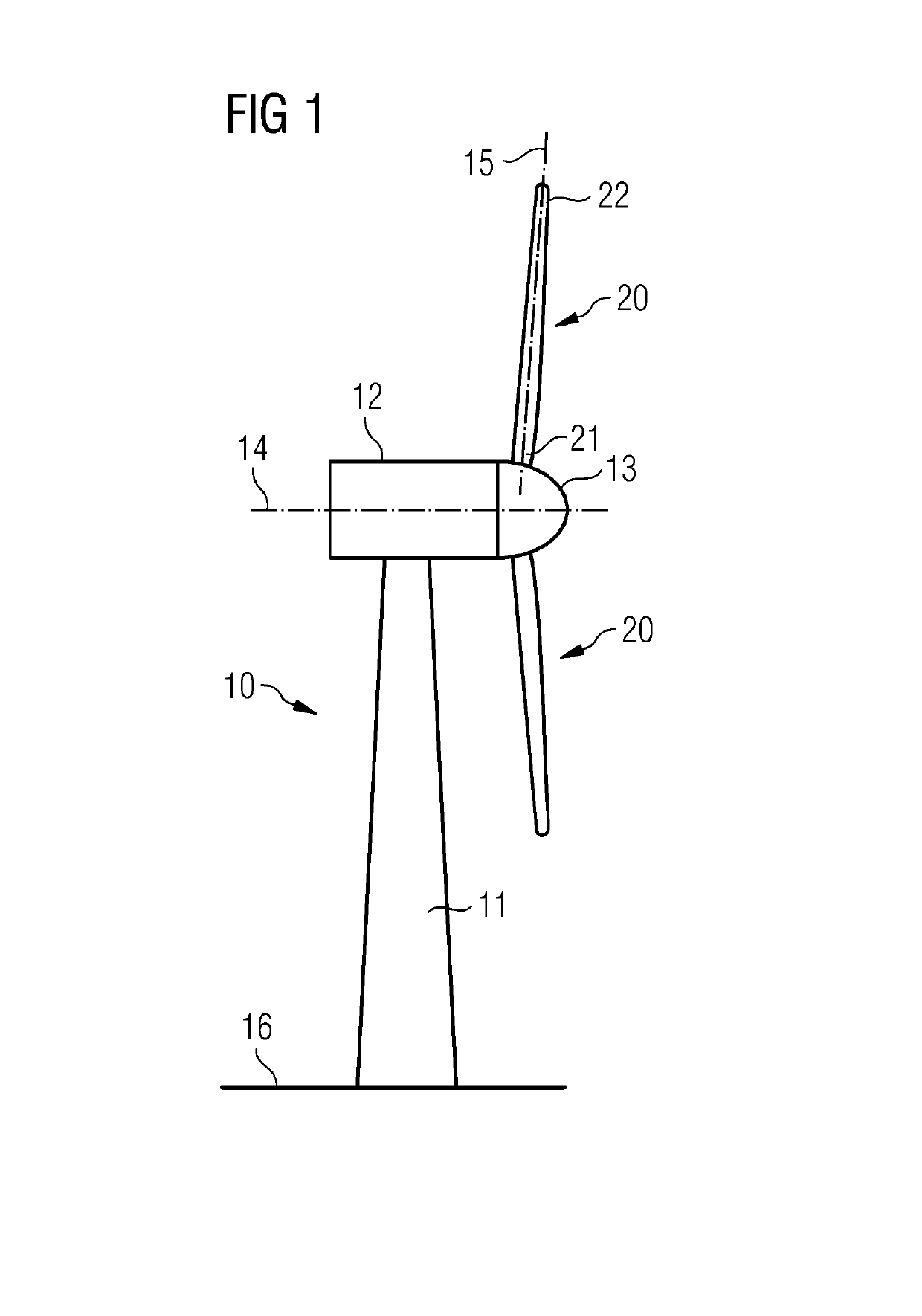
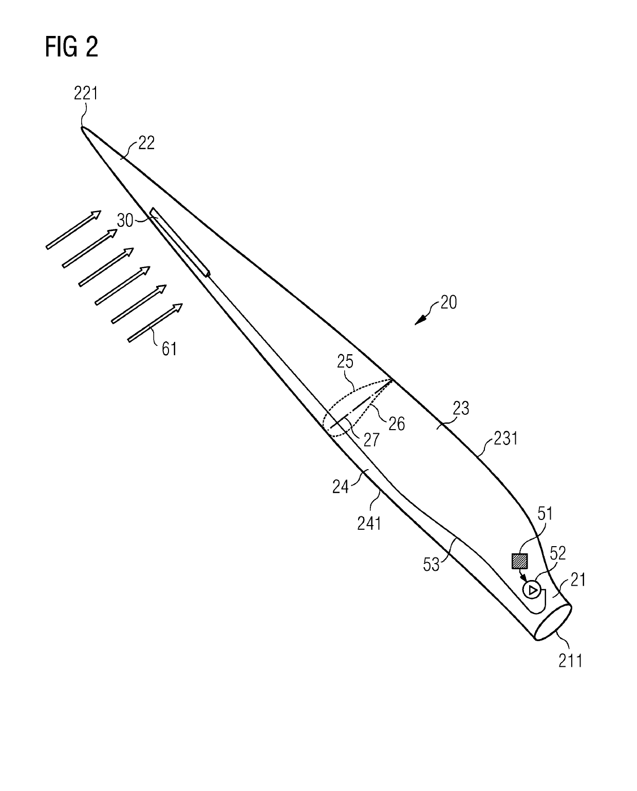
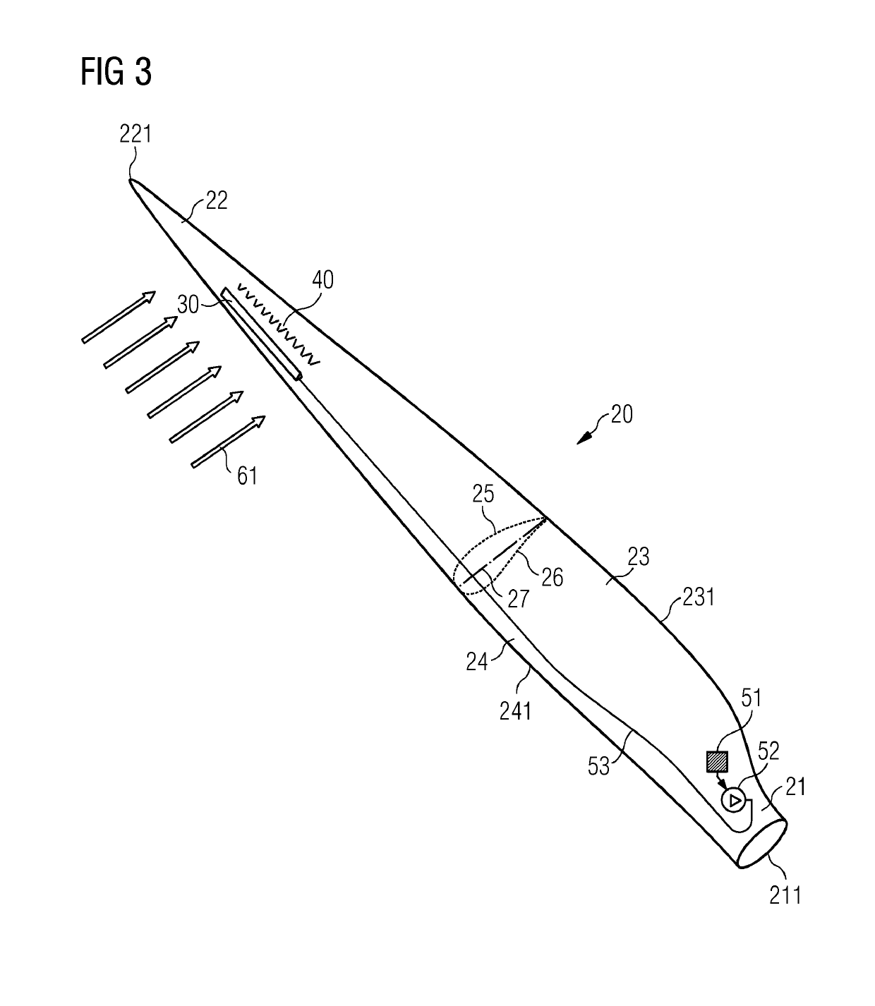
[0046]Flow regulating units are frequently more effective on the suction side compared to the pressure side of the rotor blade. Therefore, the rotor blade comprises in an advantageous embodiment the placement of the flow regulating unit and the spoiler both on the suction side of the rotor blade. This should, however, not exclude the possibility that these components may also be arranged on the pressure side of the rotor blade where they could also realize a beneficial effect on the aerodynamic properties of the rotor blade.
[0047]The advantage of posi

Problems solved by technology

This in general spoils the airflow flowing over the surface of the rotor blade (which is the reason why such a device is referred to as a spoiler) and may, depending e.g. on the chordwise position of the spoiler on the airfoil, induce stall of the airflow.
A drawback thereof is that in an emergency case, i.e. in a case where control over the aerodynamic device is lost, the pneumatic actuator collapses and moves into the configuration where it is substantially flat with regard to the surface of the rotor blade.
This, however, means that the lift of the rotor blade is high, which is generally undesired in an emergency case.
However, in the opposite case, where no pressure—neither positively nor negatively—is supplied to the hose or the cavity of the aerodynamic device, the aerodynamic device moves into a configuration where the airflow flowing across the aerodynamic device is spoiled, which leads to a drop-in lift and load of the rotor blade.
O

Method used


Image

  • Flow control arrangement for a wind turbine rotor blade
  • Flow control arrangement for a wind turbine rotor blade
  • Flow control arrangement for a wind turbine rotor blade

Examples


first embodiment

[0083]FIGS. 4 and 5 illustrate a fail-safe aerodynamic device 30 according to embodiments of the invention.

[0084]FIG. 4 shows the situation that the aerodynamic device 30 is in its first configuration. This means that in the situation as illustrated in FIG. 4, no pressure is applied to the pressure hose 31 of the aerodynamic device 30. As a consequence, the fluid 62 inside the hose 31 is at a predetermined pressure which may e.g. approach or be equal to the atmospheric pressure.

[0085]The aerodynamic device 30 comprises a first portion 34. The first portion 34 is relatively stiff and rigid. It is at least rigid enough to resist and deviate the airflow 61 which is flowing from the leading-edge section to the trailing edge section of the rotor blade. In the first configuration of the aerodynamic device 30, the first portion 34 of the aerodynamic device 30 protrudes. In other words, the first portion 34 projects away from the surface 28 of the rotor blade.

[0086]The aerodynamic device 30...

second embodiment

[0098]Finally note that care must be taken during design of the second embodiment, in particular with regard of the hinge mechanism which induces aligning the first portion with the surface 28 of the rotor blade. At the same time, it needs to be ensured that the aerodynamic device 30 in its second configuration is flat enough to not spoil the airflow, although its pneumatic actuator is inflated.

[0099]FIGS. 8 and 9 show a third embodiment of an aerodynamic device 30. Again, for sake of conciseness, similar or identical elements, which have already been introduced for the first or second embodiment of the aerodynamic device 30 will not be repeated here.

[0100]FIG. 8 shows the aerodynamic device 30 in its first configuration, i.e. in its “neutral” position without application of any pressure by the pressure supply system. The airflow 61 is spoiled, stall is induced, and, consequently, lift and load is reduced.

[0101]In contrast to FIG. 8, FIG. 9 shows the aerodynamic device 30 in its sec...

third embodiment

[0102]The similarity between the second and the third embodiment consists in that for both embodiments, a positive pressure needs to be applied to the pneumatic actuator of the aerodynamic device 30 to change the aerodynamic device 30 from its first into its second configuration.

[0103]The modification of the third embodiment with regard to the second embodiment is that in the third embodiment the aerodynamic device 30 is predominantly embedded into the shell 29 of the rotor blade. This has the advantage that drag of the aerodynamic device 30 is minimized. This is especially advantageous in the second configuration of aerodynamic device 30, when an increase as high as possible of the lift of the rotor blade is generally desired. The third embodiment of the aerodynamic device 30 proposes an attractive solution to this desire, as the aerodynamic device 30 is almost flush with the surface 28 of the rotor blade in its second configuration.

[0104]FIGS. 10 and 11 show a variant of the secon...


PUM


Abstract

A rotor blade for a wind turbine is provided. The rotor blade includes an aerodynamic device for influencing the airflow flowing from the leading-edge section of the rotor blade to the trailing edge section of the rotor blade. The aerodynamic device is mounted at a surface of the rotor blade and includes a pneumatic or hydraulic actuator, such as a hose or a cavity, of which the volume depends on the pressure of a fluid being present inside the pneumatic or hydraulic actuator. The rotor blade further includes a control unit for controlling the pressure of the fluid in the hose or the cavity of the aerodynamic device.

Description

CROSS-REFERENCE TO RELATED APPLICATIONS[0001]This application claims priority to PCT Application No. PCT / EP2017 / 058492, having a filing date of Apr. 10, 2017, which is based on European Application No. 16186403.8, having a filing date of Aug. 30, 2016, the entire contents both of which are hereby incorporated by reference.FIELD OF TECHNOLOGY[0002]The following relates to a rotor blade of a wind turbine, wherein the rotor blade comprises an aerodynamic device for influencing the airflow flowing from the leading-edge section to the trailing edge section of the rotor blade. Furthermore, the following relates to a wind turbine for generating electricity comprising at least one such rotor blade.BACKGROUND[0003]It is known to use aerodynamic devices for influencing the airflow which flows from the leading-edge section to the trailing edge section of a rotor blade of a wind turbine. Examples of such an aerodynamic device may be a spoiler or a flap. These aerodynamic devices may be configur...

Claims


Application Information

Patent Timeline
IPC IPC(8): F03D7/02F03D1/06F03D7/04
CPCF03D7/0232F03D1/0675F03D7/0276F03D7/042F03D7/0228F05B2240/311F05B2270/604F05B2270/605F03D7/022F03D7/0224F05B2270/32F05B2240/30Y02E10/74Y02E10/72F05B2240/3062F03D3/062F05B2240/122
Inventor AKAY, BUSRAENEVOLDSEN, PEDER BAYGONZALEZ, ALEJANDRO GOMEZLAURSEN, JESPER MONRADLOEVEN, ALEXSCHEURICH, FRANK
Owner SIEMENS GAMESA RENEWABLE ENERGY AS
Why Eureka
Try Eureka