Airfoil Family for a Blade of a Wind Turbine

a technology of airfoil and wind turbine, which is applied in the direction of propellers, propulsive elements, water-acting propulsive elements, etc., can solve the problems of high cost, high complexity, and high cost of fibres or flexible materials, and achieves the reduction of the overall weight of the blade, the reduction of the noise emitted by the blade in use, and the control of the configuration and dimensions accurately

Inactive Publication Date: 2009-04-23
LM GLASSFIBER
View PDF12 Cites 39 Cited by
  • Summary
  • Abstract
  • Description
  • Claims
  • Application Information

AI Technical Summary

Benefits of technology

[0007]It is the object of the invention to provide a series of profiles for a blade with good aerodynamic properties and presenting further advantages concerning the configuration of the rear edge of the blade.
[0008]Thus, the present invention relates to a series of profiles for at least a portion of a blade comprising several profiles that describe the outline of the blade transversally of its longitudinal axis, wherein at least some of the profiles in the series of profiles comprise approximately the same profile rear edge describing at least a portion of the rear edge of the blade. This enables manufacture, in a simple manner, of a rear edge in one piece for the entire or long lengths of the blade, which is advantageous, since it is hereby possible to manufacture the rear edge expediently and inexpensively, eg by pultrusion or extrusion. By manufacturing the rear edge of the blade separately, its configuration and dimensions can be controlled accurately, which may be extremely difficult and cost-intensive with current methods of manufacture. The blade rear edge produced can thus either be mounted on the remainder of the blade or optionally be moulded integrally there with, and timewise heavy and cost-intensive production phases in the conventional production, such as sanding and painting, can be obviated. Likewise, the invention enables that the rear edge of the blade can be made of another material than the blade as such. For instance a lighter material, whereby the overall weight of the blade can be reduced considerably, or a flexible material such as rubber. The latter is advantageous, on the one hand by reducing the noise emitted by the blade in use and, on the other, by making the rear edge less receptive towards scratches and damage in connection with transport and handling in general. Should the rear edge be damaged or worn, it is also simple to replace. By configuring the rear edge as a separate part applied onto the remainder of the blade structure, the strains and tensions in the rear edge can also be reduced considerably, whereby the blade structure is generally considerably enhanced. Moreover, a rear edge as described above can also advantageously be combined with blades in accordance with the owl's wing principle. Here the noise emission of the blade is reduced considerably in that fibres of flexible material are applied onto the blade, protruding beyond the rear edge. It is a major drawback of such blades that such fibres or flexible material are quickly worn and therefore necessitate maintenance or replacement. However, this is not a major problem when a blade with a rear edge according to the present invention is concerned, since, here, it is a simple and quick procedure to replace the entire rear edge of the blade, if necessary.
[0011]Yet an embodiment relates to a series of profiles for a blade, wherein at least some of the profiles of the series of profiles are determined on the basis of a number of different, alternative profile rear edges. Hereby the series of profiles is designed to be optimal in case of a number of different rear edges (optionally optimal in the light of different criteria for the different profile rear edges). Hereby the same primary-blade structure can be combined with different rear edges and hence be designed optimally for different aerodynamic properties. The same blade mould can thus be used to manufacture different types of blades. Likewise a blade can be adapted to the specific needs or desires of a customer, quite simply by selection of a suitable rear edge. For instance, a blunt rear edge can be replaced by a sharp rear edge; the blade can be made wider by selecting a correspondingly wider rear edge, whereby the optimal number of revolutions for the blades is reduced, reducing the noise accordingly.
[0014]According to one embodiment of the invention, at least a portion of the rear edge of the blade is made in one piece and / or manufactured from another material than the remainder of the blade surface. According to yet an embodiment, the material may be a flexible material, such as eg rubber. As mentioned above, hereby a quieter blade is accomplished as well as a rear edge which is not so easily damaged during transport.

Problems solved by technology

By manufacturing the rear edge of the blade separately, its configuration and dimensions can be controlled accurately, which may be extremely difficult and cost-intensive with current methods of manufacture.
It is a major drawback of such blades that such fibres or flexible material are quickly worn and therefore necessitate maintenance or replacement.

Method used


Image

  • Airfoil Family for a Blade of a Wind Turbine
  • Airfoil Family for a Blade of a Wind Turbine
  • Airfoil Family for a Blade of a Wind Turbine

Examples


Embodiment Construction

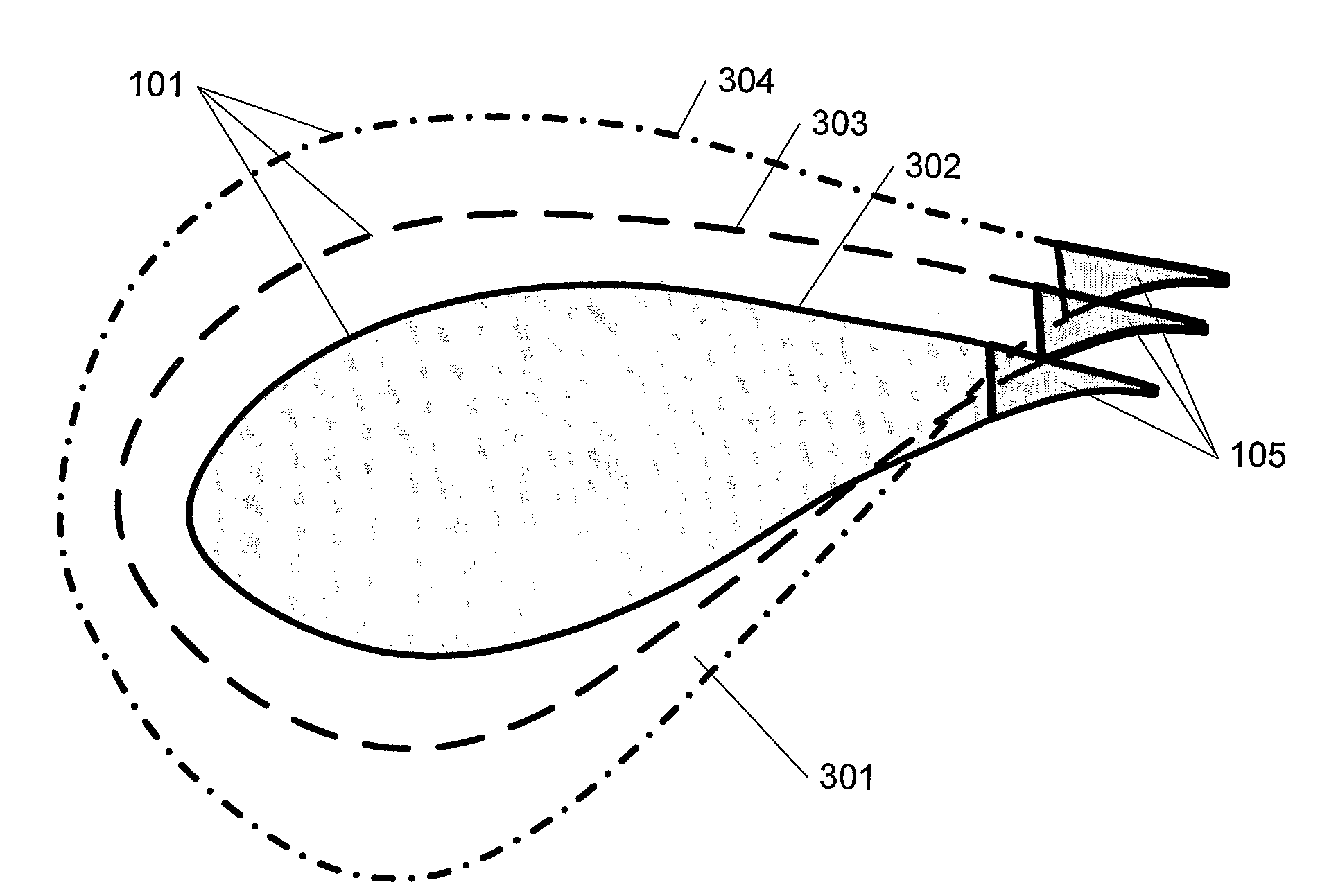
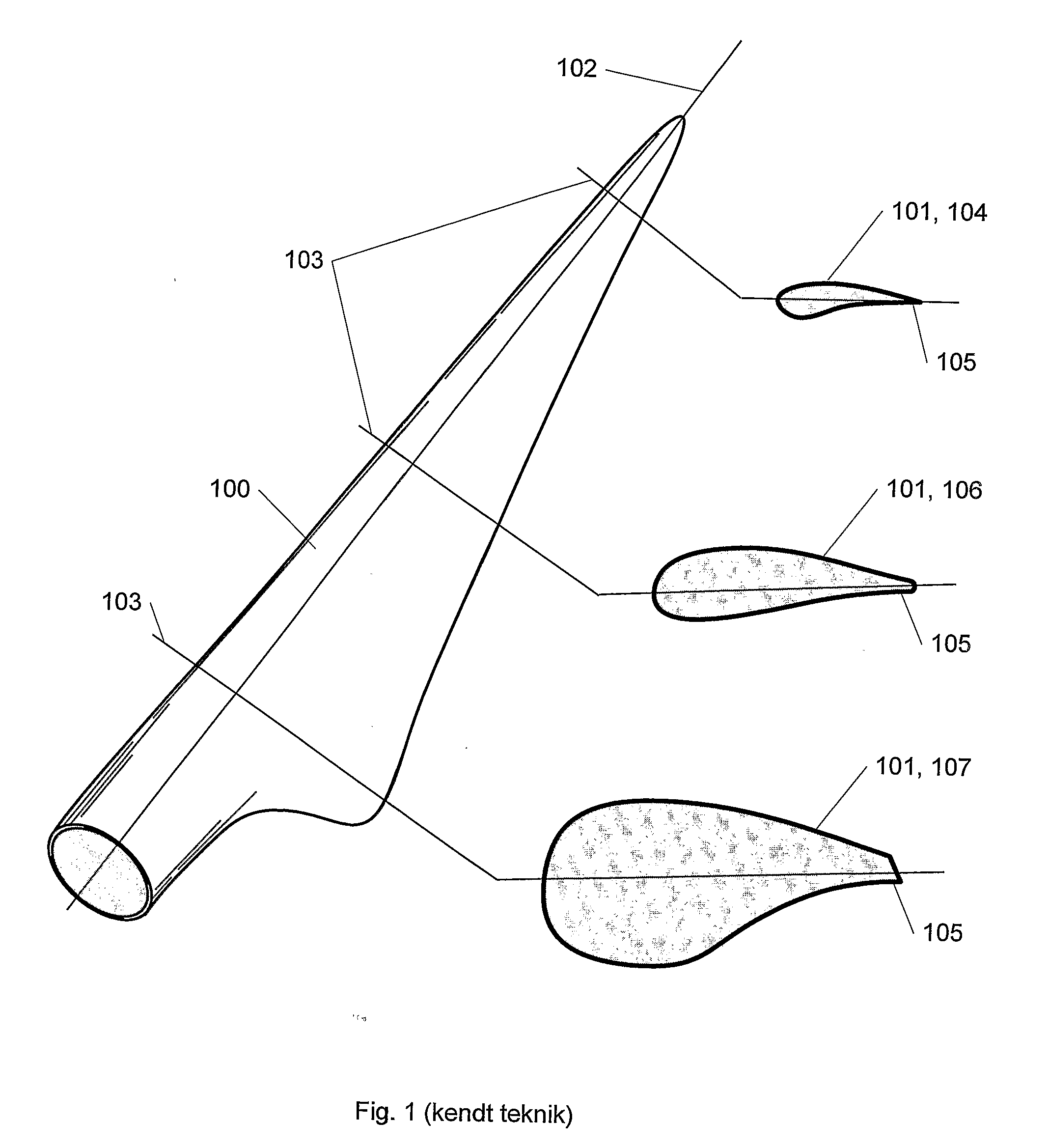
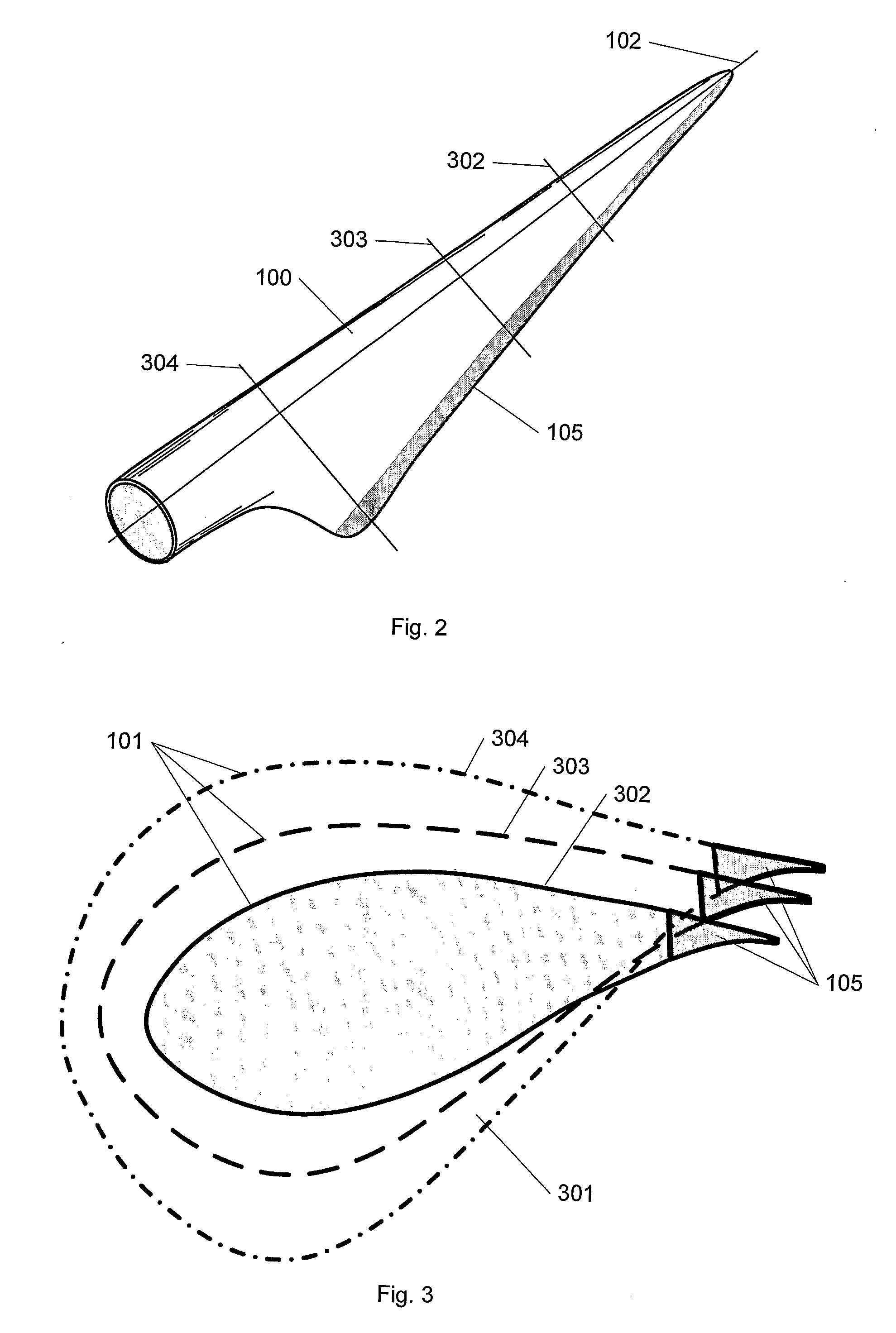
[0027]FIG. 1 shows a blade 100 for a wind turbine according to the prior art. The blade is described by a number of profiles 101 as outlined next to the blade. Each profile 101 indicates the outer contour of the blade 100 in a cross-sectional view in a given position down along the longitudinal axis 102 of the blade corresponding to a cross-section along the marked lines 103. Series of profiles for wings of aircrafts often consist of the same type of profile which is then scaled to size outwards of the wing. This is often not the case with blades for wind turbines which may instead be given by series of profiles featuring different types of profiles, between which the surface of the blade is thus interpolated or blended, and a smooth transition is created between the various profiles. This is illustrated by the blade shown in FIG. 1 which, in a position most distally at the blade tip, is defined by a profile 104 featuring a sharp rear edge 105. A sharp rear edge is advantageous in t...


PUM

PropertyMeasurementUnit
widthaaaaaaaaaa
widthaaaaaaaaaa
widthaaaaaaaaaa

Abstract

A wind turbine rotor blade comprising a series of profiles is presented, which series of profiles comprises a number of profiles describing the outline of the blade transversally of its longitudinal axis, wherein some of the profiles of the series of profiles comprise approximately the same profile rear edge which describes at least a portion of the rear edge of the blade. The rear edge of the blade is configured in one piece and / or of a flexible material. Moreover a method of designing a series of profiles for a wind turbine rotor blade is presented.

Description

[0001]The invention relates to a series of profiles for at least a portion of a blade comprising several profiles describing the outline of the blade transversally to its longitudinal axis. The invention also relates to a method of designing a series of profiles and a blade featuring such series of profiles.BACKGROUND[0002]Blades / wings for aircrafts, helicopters, wind turbines, etc., are made from series of profiles that describe the cross section of the blade / wing in various positions along the length of the blade / wing. The profiles are determined on the basis of parameters such as eg optimal lift coefficients at specific height / width-ratios, or, for a blade for wind turbines, more generally to provide maximal power yield at specific rates of rotation. Wings for aircrafts are often defined on the basis of the same profile in all cross-sections, but scaled in size. This is not the case for blades for wind turbines that are often built over a series of profiles with a number of diffe...

Claims


Application Information

Patent Timeline
Patent Type & Authority Applications(United States)
IPC IPC(8): F03D1/06
CPCF03D1/0641F03D1/0675F05B2240/301Y02E10/721F05B2280/4004F05C2225/02F05B2240/311Y02E10/72
Inventor GRABAU, PETER
Owner LM GLASSFIBER
Why Eureka
Try Eureka