Turbine airfoil with trailing edge

a technology of trailing edge and turbine, which is applied in the direction of liquid fuel engines, vessel construction, marine propulsion, etc., can solve the problems of airfoil with a surface contour that is aerodynamically undesirable, slow acceleration, and higher specific fuel consumption, and achieve the effect of improving the sensitivity to spallation

Active Publication Date: 2011-12-06
FLORIDA TURBINE TECH
View PDF11 Cites 36 Cited by
  • Summary
  • Abstract
  • Description
  • Claims
  • Application Information

AI Technical Summary

Benefits of technology

[0011]It is an object of the present invention to provide for

Problems solved by technology

Small exit areas also cause slower accelerations because the compressor will have to work against an increased back pressure.
Increasing the nozzle diaphragm area will result in faster engine acceleration, less tendency to stall, but higher specific fuel consumption.
This produces an airfoil with a surface contour that will be aerodynamically undesirable.
The prior art aerodynamic

Method used


Image

  • Turbine airfoil with trailing edge
  • Turbine airfoil with trailing edge
  • Turbine airfoil with trailing edge

Examples


second embodiment

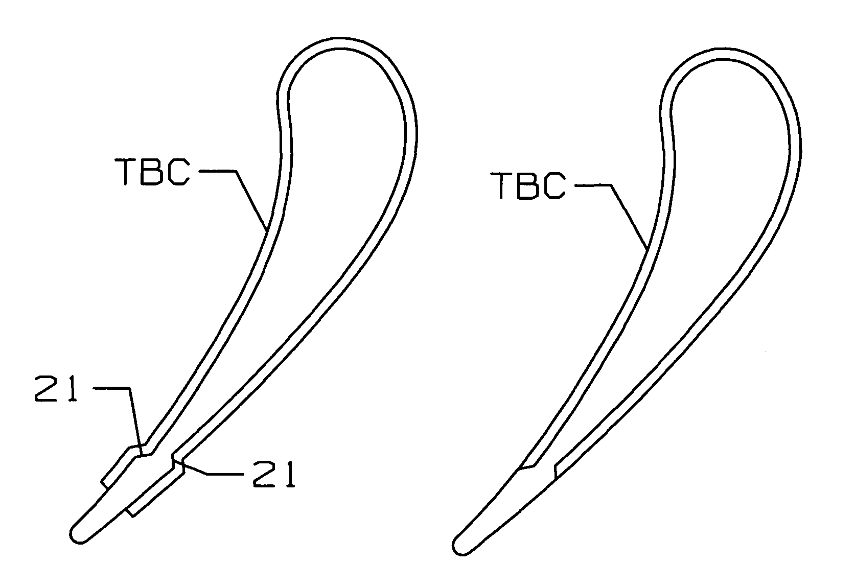
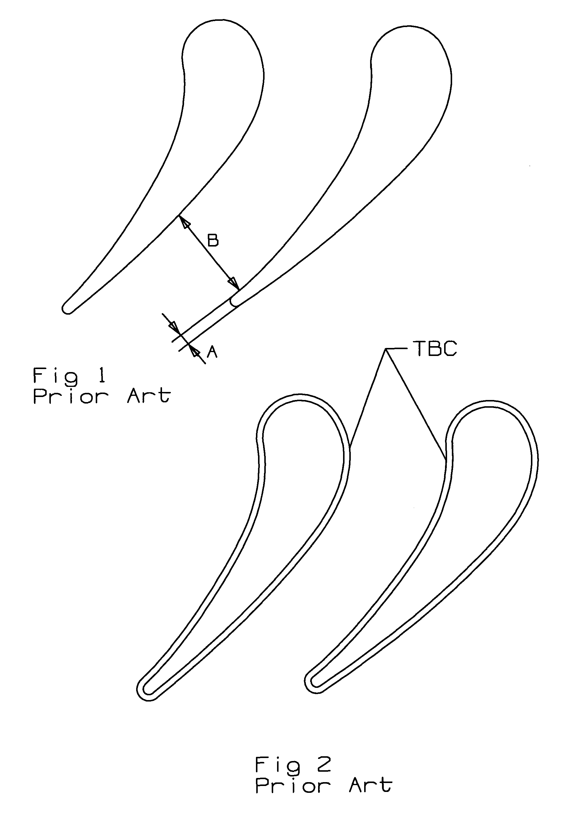
[0023]the present invention is shown in FIG. 5. The final airfoil outer contour is shown in FIG. 5b in which the coating extends around the airfoil with a thickness and tapers off at the trailing edge region to a thickness of zero. The metal airfoil outer contour is reduced so that the coating will provide the final desired outer airfoil contour. In the FIG. 5 embodiment, a local increase in the airfoil trailing edge thickness is formed to accommodate strip masking. The tapered outer surface (21 on the pressure side and 22 on the suction side) at the trailing edge region allows for the TBC to smoothly progress from normal thickness to a zero thickness while the outer airfoil contour (metal surface and TBC) remains smooth. The relatively thick TBC will then blend into the outer airfoil surface and maintain the ideal surface contour critical to aerodynamic performance. Control of the trailing edge geometry is critical to aerodynamic performance, particularly on the pressure side.

[0024...

third embodiment

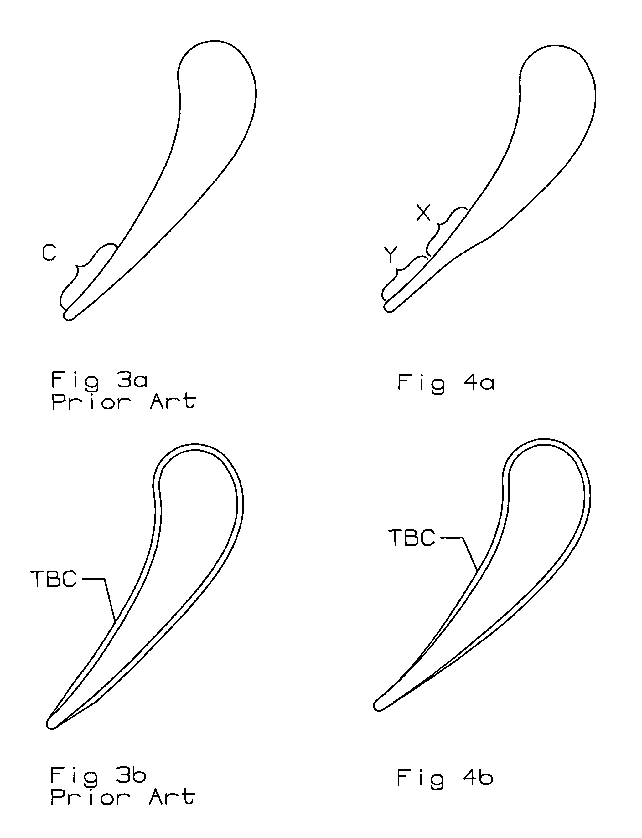
[0025]the present invention is shown in FIG. 6. Control of the trailing edge geometry is critical to aerodynamic performance. To improve control of the coated trailing edge contour, the underlining airfoil is formed with locally raised bumps or tear drops 31 which will enable the coating to be stoned or lapped to the ideal contour. A number of these raised bumps 31 are located along the airfoil trailing edge and each has a height equal to the desired thickness of the coating. The bumps 31 are preferably cast into the airfoil surface when the airfoil is cast. The coating is then applied over the bumps 31 to cover the bumps 31 such that the bumps 31 are no longer visible. When the coating has hardened, the outer surface of the coating is removed by the stoning or lapping process down to the level of the bumps 31 so that the remaining coating has the desired thickness. The raised bumps 31 can be used a visual indicator of when the coating is at the desired thickness, or can be used to ...


PUM


Abstract

A turbine airfoil with a relatively thick TBC applied over the airfoil surface. The airfoil has a surface contour on the trailing edge region with a forward end having a large amount of taper and a rearward end with less taper such that a substantially constant wall thickness is formed in the rearward end. The TBC is applied over the airfoil surface and tapers off at the trailing edge ends on the pressure side and the suction side walls to produce an ideal surface contour on the airfoil. In another embodiment, the airfoil surface includes a tapered section at the trailing edge region, and the TBC is applied over the taper so that an over-coating is formed. The TBC over-coating is then removed and a smooth and ideal surface contour is produced along the airfoil surface. Small raised bumps each having a height of the desired thickness of the TBC to be applied over the respective bump is used to control the finished thickness of the TBC.

Description

BACKGROUND OF THE INVENTION[0001]1. Field of the Invention[0002]The present invention relates generally to a gas turbine engine, and more specifically to a throat formed between adjacent stator vanes.[0003]2. Description of the Related Art including information disclosed under 37 CFR 1.97 and 1.98[0004]In a gas turbine engine, the turbine converts the energy of the passing hot gas flow into mechanical energy to drive the rotor shaft. In an aero engine, the turbine provides a majority of the mechanical power to the fan. In an industrial gas turbine (IGT) engine, the majority of power delivered to the rotor shaft is used to drive an electric generator for electrical power production. In either case, the efficiency of the engine is directly related to the efficiency of the turbine.[0005]One method of improving the efficiency of the turbine is to place a row of stator or guide vanes directly upstream from a stage of rotor blades in order to direct the hot gas flow into the rotor blades ...

Claims


Application Information

Patent Timeline
IPC IPC(8): F01D5/18
CPCF01D5/288F05B2230/90F05D2230/90
Inventor RAWLINGS, CHRISTOPHER K.
Owner FLORIDA TURBINE TECH
Why Eureka
Try Eureka