Aerodynamic trucking systems

Active Publication Date: 2014-05-20
STREHL LLC
View PDF28 Cites 34 Cited by
  • Summary
  • Abstract
  • Description
  • Claims
  • Application Information

AI Technical Summary

Benefits of technology

[0013]In addition, it provides such a cargo trailer system wherein at least one adjustable portion of such at least one support comprises at least one rigid channel structured and arranged to rigidly support the at least one air-flow director. And, it provides such a cargo trailer system wherein such at least one first support rotator further comprises: fixed to such at least one platform attacher in an orientation coaxial with the rotational axis perpendicular to the at least one cargo-supporting platform, at least one pivot bar; wherein such at least one rigid channel is pivotally engaged on such at least one pivot bar; wherein such at least one spring biaser comprises at least one helical-type torsion spring structured and arranged to apply at least one spring force concurrently to such at least one platform attacher and such at least one rigid channel to bias such at least one rigid channel toward at least one position orienting the at least one air-flow director in the at least one useful aerodynamic rest-position.
[0014]Further, it provides such a cargo trailer system wherein such at least one support rotator adjuster comprises: at least one threaded member threadably engaged within such at least one rigid channel; wherein such at least one threaded member comprises at l

Problems solved by technology

Most large long-haul cargo trailers exhibit less than optimal aerodynamic performance during highway operation.
At highway speeds, conventional trailers develop a substantial amount of turbulent airflow in the region between the axles below the trailer box.
This turbulence results in significant aerodynamic drag, incr

Method used


Image

  • Aerodynamic trucking systems
  • Aerodynamic trucking systems
  • Aerodynamic trucking systems

Examples


Embodiment Construction

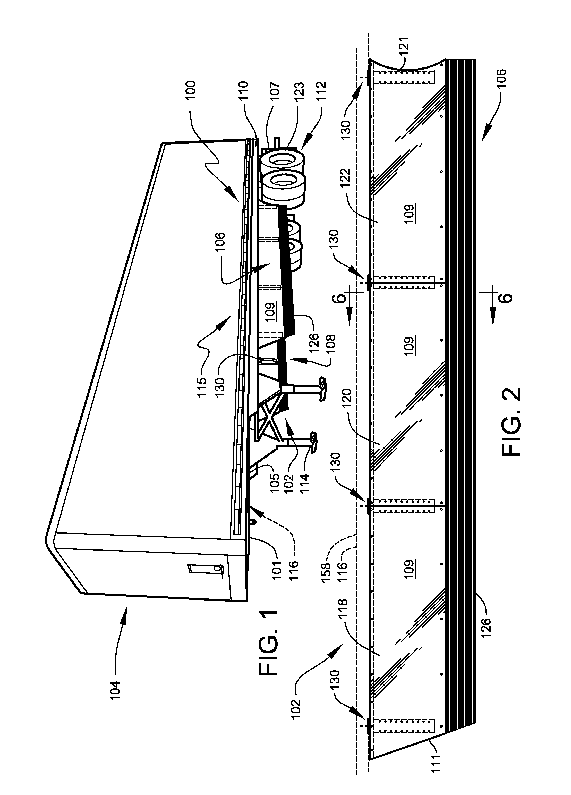
[0039]Aerodynamic trucking system 100 preferably comprises a group of system embodiments designed to improve the aerodynamic performance of wheeled cargo haulers at speed, particularly large road-going trailers serving long-haul cargo transport operations. The fuel efficiency of a motor-driven vehicle is closely related to the aerodynamic configuration of the vehicle, particularly with respect to the amount of air turbulence generated during movement of the vehicle through the air. The greater the air turbulence created by the vehicle the greater the resistance, and the more fuel required to move the vehicle.

[0040]Preferred embodiments of the aerodynamic trucking system 100 preferably function to manage airflow around and under a semi-type cargo trailer, with the achieved goal of significantly reducing aerodynamic turbulence during operation. Testing of the system embodiments showed a significant reduction in turbulent airflow in and around the trailer, resulting in a corresponding ...


PUM


Abstract

A system of aerodynamic skirt fairings designed to minimize aerodynamic drag and maintain smoother air flow over highway-operated long-haul tractor-trailer vehicles.

Description

CROSS-REFERENCE TO RELATED APPLICATION[0001]The present application is a continuation-in-part of, and is related to and claims priority from, application Ser. No. 13 / 117,891 filed May 27, 2011, entitled “AERODYNAMIC TRUCKING SYSTEMS”, which prior application Ser. No. 13 / 117,891 is related to and claims priority from prior provisional application Ser. No. 61 / 349,183, filed May 27, 2010, entitled “AERODYNAMIC TRUCKING SYSTEMS”; and, which prior application Ser. No. 13 / 117,891 is related to and claims priority from prior provisional application Ser. No. 61 / 374,572, filed Aug. 17, 2010, entitled “AERODYNAMIC TRUCKING SYSTEMS”; and, the present application is related to and claims priority from prior provisional application Ser. No. 61 / 639,830, filed Apr. 27, 2012, entitled “AERODYNAMIC TRUCKING SYSTEMS”; the contents of all of which are incorporated herein by this reference and are not admitted to be prior art with respect to the present invention by the mention in this cross-reference ...

Claims


Application Information

Patent Timeline
IPC IPC(8): B62D35/00
CPCB62D35/001B62D35/02Y10S180/903B62D35/008Y02T10/88Y02T10/82
Inventor SENATRO, RICHARD, P.
Owner STREHL LLC
Why Eureka
Try Eureka