Stabilization of closed loop operation of a torsional hinged device

a technology of torsional hinged mirrors and closed loops, which is applied in the field of sweeping light beam stabilization methods and apparatus, can solve the problems of low frequency jitter, produced artifacts in high quality printed images, and vibration modes of galvanometers or torsional hinged mirrors, so as to reduce amplification or pumping, prevent the amplification of undesirable vibrational modes, and the effect of low jitter

Active Publication Date: 2006-01-05
TEXAS INSTR INC
View PDF2 Cites 7 Cited by
  • Summary
  • Abstract
  • Description
  • Claims
  • Application Information

AI Technical Summary

Benefits of technology

[0005] A solution to the jitter and stability problems discussed above is addressed by the present invention by producing an asymmetry in the mirror mass balance or an asymmetry in the torque producing drive fields. Such asymmetry introduces a slight lateral mirror motion along with the primary rotation or oscillation that is sufficient to change the error signals produced by the position sensor and thus substantially reduce amplification or pumping of the undesirable mode by the controller system. Consequently, the mirror's motion is stabilized and amplification of the undesirable vibrational modes is prevented. More specifically, the slight lateral motion has negligible impact on the scan beams velocity profile, yet allows closed loop control with low jitter and high proportional gain values. Thus, the “slight” lateral motion leaves sufficient margin to control real world systems and environmental disturbances.

Problems solved by technology

These amplitude variations create low frequency jitter in the scan beam that in turn produced artifacts in high quality printed images.
Unfortunately, galvanometer or torsional hinged mirrors have vibrational modes other than the oscillation or rotational mode that produces the scanned beam.
Therefore, if the control or feedback loop produces changes in the frequency components of the drive mechanism that excite the mirror's non-rotational modes, then undesirable vibrational modes can be excited.
The excitation of some vibrational modes can produce beam motion, which can in turn produce an even larger error signal.
The feed back loop may then try to suppress this larger signal by further increasing the drive correction, which further exacerbates the error.
This unstable process amplifies or pumps the undesirable mode and the controlled system may oscillate or even diverge.
In practice, this problem is observed as an oscillation in the error signal and mirror jitter at high proportional loop gain settings.

Method used


Image

  • Stabilization of closed loop operation of a torsional hinged device
  • Stabilization of closed loop operation of a torsional hinged device
  • Stabilization of closed loop operation of a torsional hinged device

Examples


Embodiment Construction

[0018] The making and using of the presently preferred embodiments are discussed in detail below. It should be appreciated, however, that the present invention provides many applicable inventive concepts that can be embodied in a wide variety of specific contexts. The specific embodiments discussed are merely illustrative of specific ways to make and use the invention, and do not limit the scope of the invention.

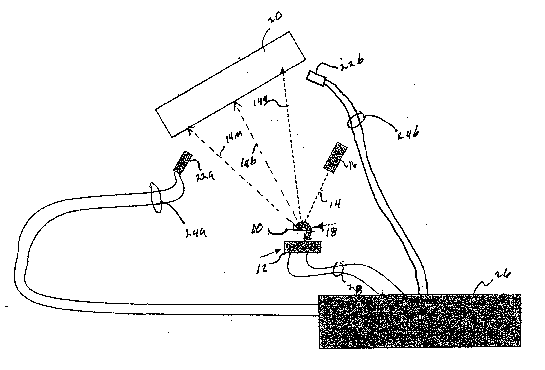
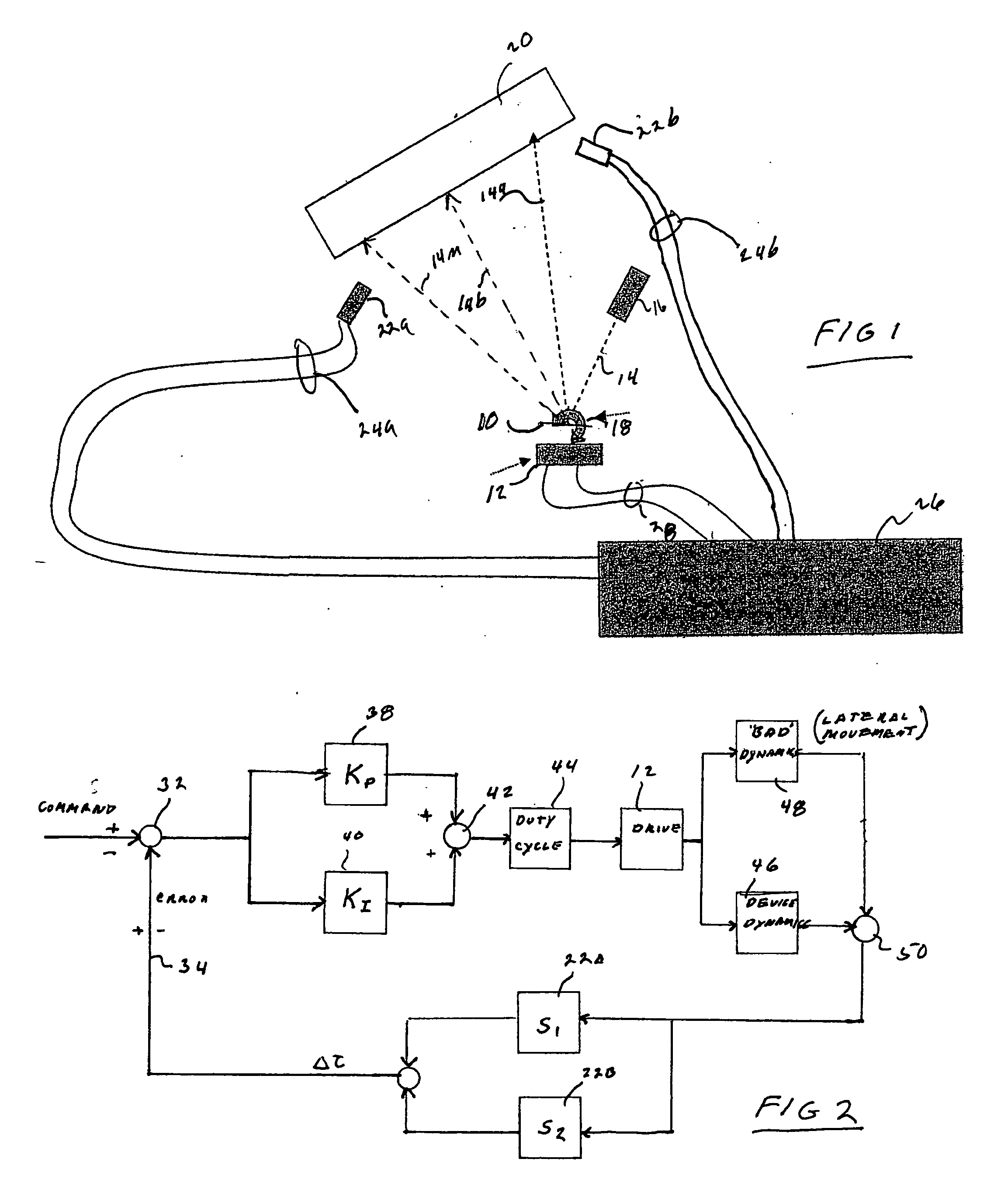
[0019] Referring now to FIG. 1, there is illustrated a simplified system diagram of a torsional hinged pivoting device that will benefit from the teachings of the present invention. The illustrated system is a laser printer using a resonant torsional hinged mirror as the printer “drive engine”. As shown, the printer system comprises a resonant scanning device 10, which in the illustrative embodiment is a mirror. The scanning device 10 is driven by the application of a drive torque to the pivoting device, such as the scanning device or mirror 10. Although various techniques ...


PUM


Abstract

Apparatus and methods for removing jitter and stabilizing the feed back system of a torsional hinged device with minimal changes to the system. The stabilization is accomplished by introducing a selected amount of lateral motion (in addition to the rotational motion) by creating asymmetry in the oscillating device or the drive torque applied to the device.

Description

[0001] This application claims the benefit of U.S. Provisional Application No. 60 / 584,294, filed on Jun. 30, 2004, entitled Stabilization Of MEMS Mirrors In Closed Loop Operation, which application is hereby incorporated herein by reference.TECHNICAL FIELD [0002] The present invention relates to a scanning apparatus and to methods and apparatus for stabilizing the velocity profile of such a scanning apparatus. More particularly, the present invention relates to methods and apparatus for stabilizing the velocity profile of a sweeping light beam used in printing and display devices. BACKGROUND [0003] Torsional hinged or galvanometer type mirrors provide an inexpensive alternate mechanism to rotating polygon shaped mirrors that generate a sweeping light beam suitable for use with visual displays and high speed printers. As will be appreciated by those skilled in the art, in order to print high quality images with a laser printer, the mirror which scans or sweeps the light beam across a...

Claims


Application Information

Patent Timeline
Patent Type & Authority Applications(United States)
IPC IPC(8): G02B26/08G02B7/182
CPCG02B26/085H04N2201/0476G09G3/02G02B26/105
Inventor TURNER, ARTHUR MONROEHEATON, MARK W.
Owner TEXAS INSTR INC
Why Eureka
Try Eureka