Variable transmission power for fill level measuring

a transmission power and fill level technology, applied in the field of fill level measuring, can solve the problems of affecting the quality of signal evaluation and thus the measuring result, the overdrive of the receiving unit, and the inability to accurately measure, so as to reduce the transmission output and less energy.

Active Publication Date: 2013-03-26
VEGA GRIESHABER GMBH & CO
View PDF19 Cites 5 Cited by
  • Summary
  • Abstract
  • Description
  • Claims
  • Application Information

AI Technical Summary

Benefits of technology

[0010]It should be noted that the electronics module issues similar signal shapes both in relation to the first and in relation to the second transmission outputs so that a choice between the two transmitting signals may be made for measuring a fill level, without this requiring extensive processing.
[0013]There may be an advantage, when compared to reducing the transmission output by means of an attenuation element with variable attenuation, in that, among other things, less energy may be consumed at a low transmission output.
[0019]In other words, there is no need to switch the amplifier off in order to reduce amplification; instead, the amplifier is bypassed by way of the detour line. In this way a situation may be prevented in which the input adaptations and output adaptations of the electronics module change as a result of switching off the high-frequency amplifier by way of an operating voltage. In this manner the pulse form of the microwave pulses (transmitting signals) may to a large extent be kept constant.

Problems solved by technology

If the amplitude is low, for example because the measuring signal has been considerably attenuated on its path from the transmitter to the product and back, or if the product provides poor reflection, the quality of signal evaluation and thus the measuring result suffer.
In contrast to this, if the amplitude of the received signal is excessive, the receiving unit often overdrives.
This subsequently results in incorrect measuring.

Method used


Image

  • Variable transmission power for fill level measuring
  • Variable transmission power for fill level measuring
  • Variable transmission power for fill level measuring

Examples


Embodiment Construction

[0052]The illustrations in the figures are diagrammatic and not to scale.

[0053]In the following description of the figures the same reference characters are used for identical or similar elements.

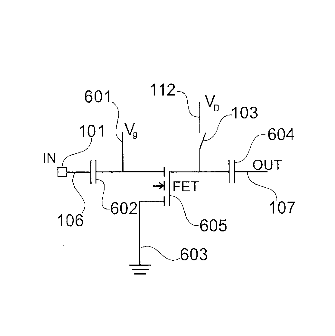
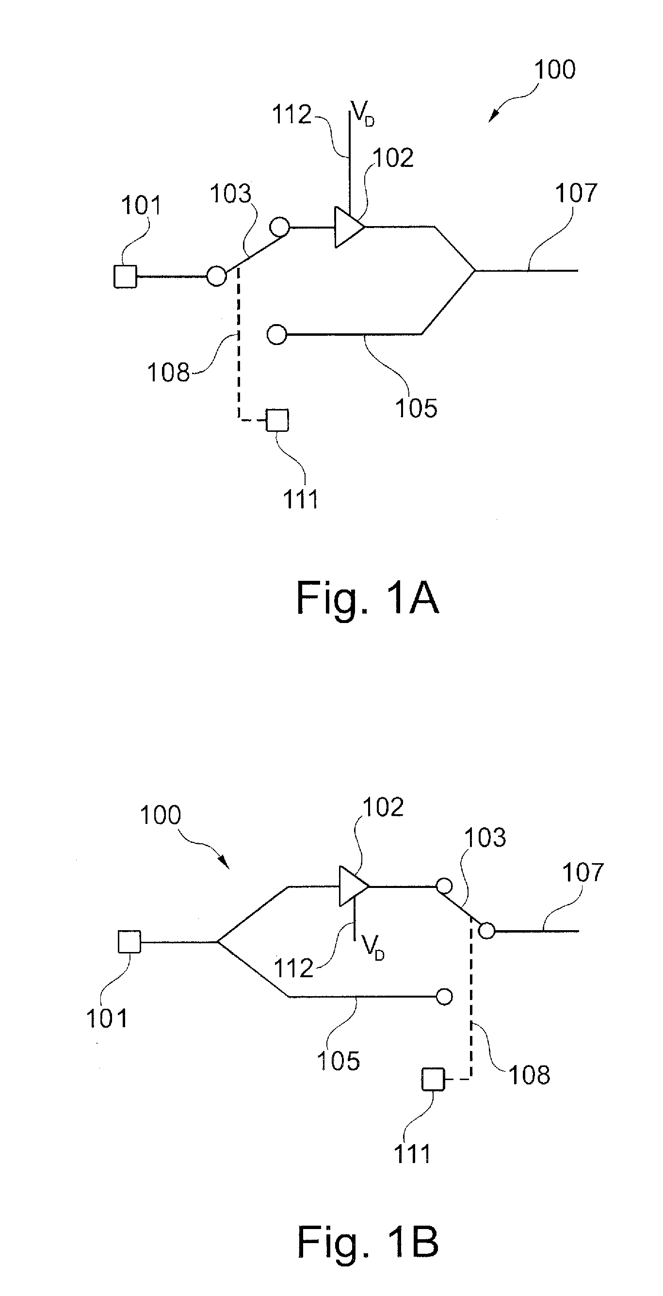
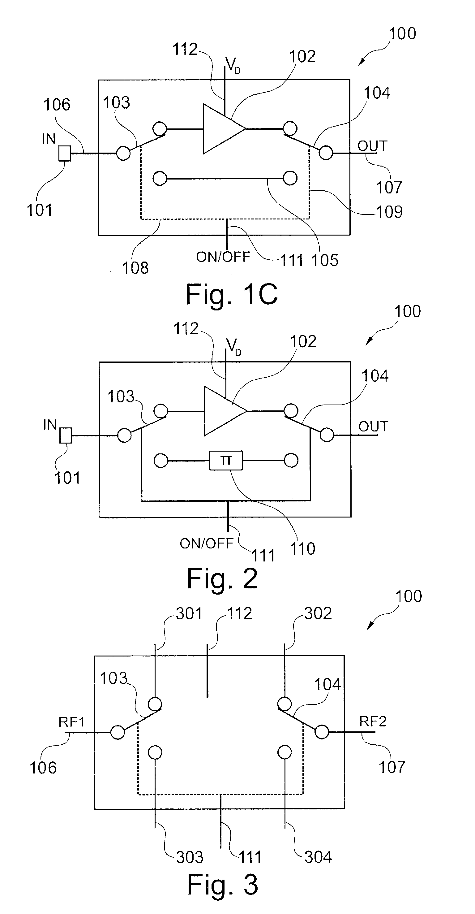
[0054]FIG. 1A shows a block diagram of an electronics module 100 that comprises a signal switch 103 and a detour line 105. A signal source 101 is provided which generates the transmitting signal.

[0055]Depending on the desired transmission output at the output 107 of the electronics module 100, the signal switch 103 is switched either so that the detour line 105 is used for conducting the transmitting signal, or (as shown) so that the upper signal path is used.

[0056]In the upper signal path a high-frequency amplifier 102 is incorporated which is used to amplify the output of the transmitting signal. This amplifier 102 is fed by way of a drain voltage VD112.

[0057]The signal switch 103 is controlled or switched by way of the control unit 111 and the control line 108.

[0058]In this way it may th...


PUM


Abstract

The transmission power of a fill level radar is varied in that the transmission power is switched, by a signal switch, from a first transmission power to a second transmission power. This switching takes place, for example, by bypassing the high-frequency amplifier or by switching off a drain voltage.

Description

REFERENCE TO RELATED APPLICATION[0001]This application claims the benefit of the filing date of EP Patent Application Serial No. 08 163 708.4 filed on 4 Sep. 2008 and U.S. Provisional Patent Application Ser. No. 61 / 094,156 filed on 4 Sep. 2008, the disclosure of which applications is hereby incorporated herein by reference.FIELD OF THE INVENTION[0002]The present invention relates to fill level measuring. In particular, the invention relates to an electronics module for a fill level radar for varying the transmission power of a transmitting signal, to a fill level radar, to the use of an electronics module for fill level measuring, as well as to a method for varying the transmission power of a transmitting signal.TECHNOLOGICAL BACKGROUND[0003]Known fill-level measuring devices for contactless measuring comprise an antenna that emits and receives signals (radar signals, microwaves or ultrasound) in order to determine the fill level of a medium, e.g. in a product container. In such a s...

Claims


Application Information

Patent Timeline
Patent Type & Authority Patents(United States)
IPC IPC(8): G01S13/08G01F23/284
CPCG01F23/284G01S7/282
Inventor CORBE, BERNHARDFISCHER, MICHAELMUELLER, CHRISTOPHSCHULTHEISS, DANIEL
Owner VEGA GRIESHABER GMBH & CO
Why Eureka
Try Eureka