
Thermally assisted magnetic recording head and magnetic recording apparatus

a technology of magnetic recording and magnetic recoding, which is applied in the field of magnetic recording apparatuses and magnetic recoding heads that are heated and assisted, to achieve the effects of suppressing the fluctuation of optical power, enhancing coupling efficiency, and enhancing coupling efficiency

Inactive Publication Date: 2008-08-28
HITACHI LTD
View PDF5 Cites 93 Cited by
  • Summary
  • Abstract
  • Description
  • Claims
  • Application Information

AI Technical Summary

Benefits of technology

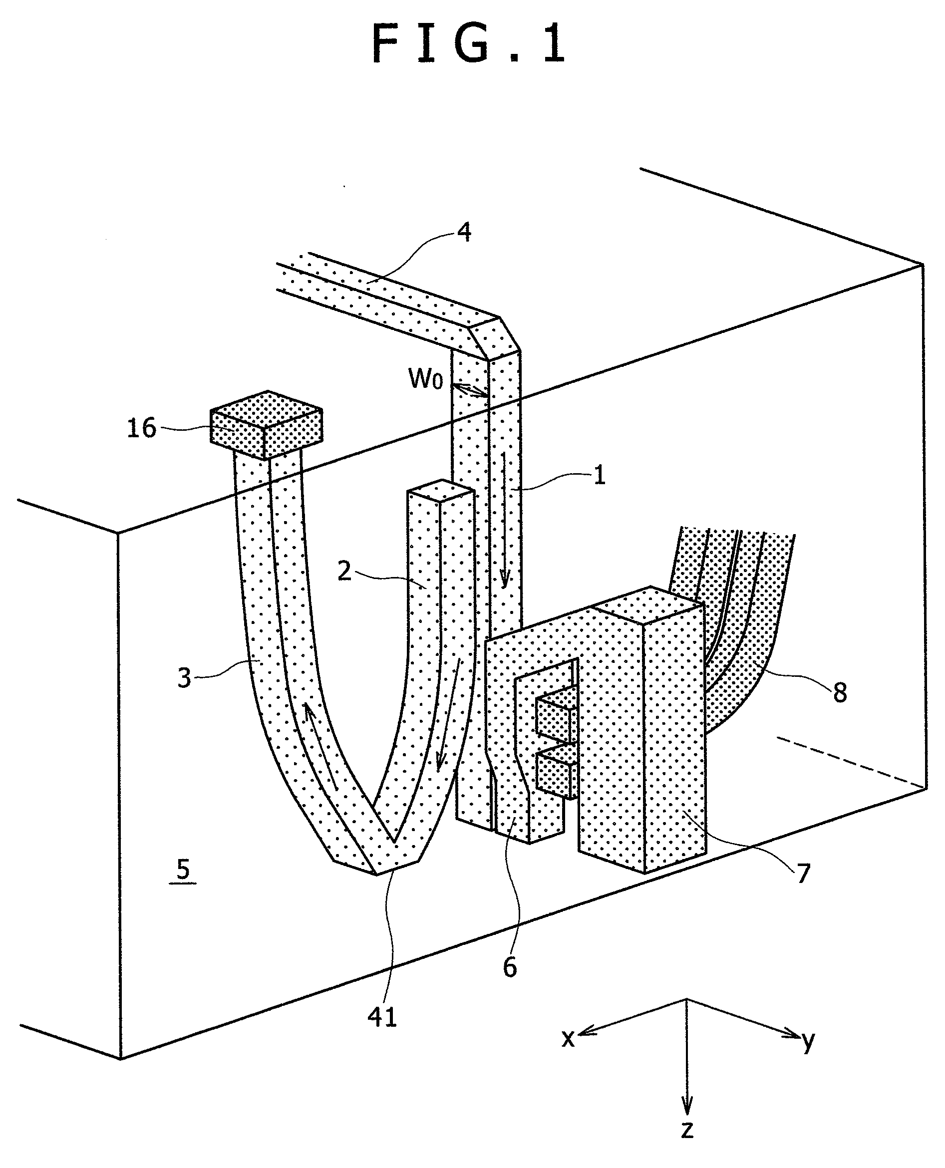
[0014]In the magnetic recording apparatus having the thermally assisted magnetic recording head mounted thereon, the output of the semiconductor laser is decreased when the amount of light incident to the photodetector is large, while the output of the semiconductor laser is increased when the amount of light incident to the photodetector is small. By constituting a feedback loop as described above, the intensity of the light propagated in the first waveguide is kept constant.
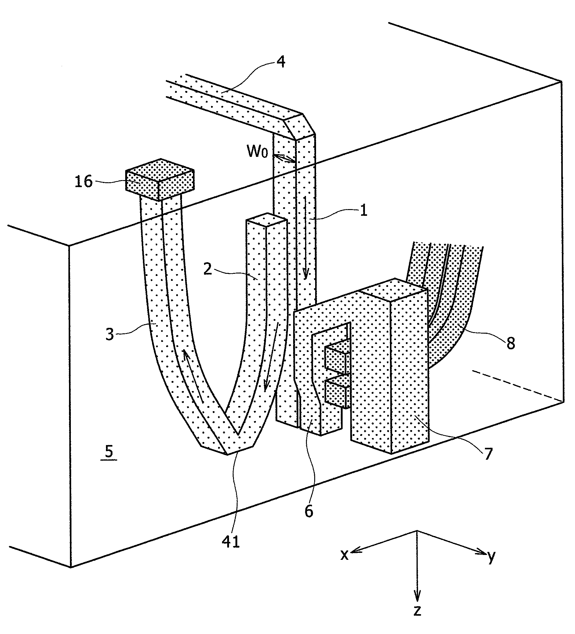
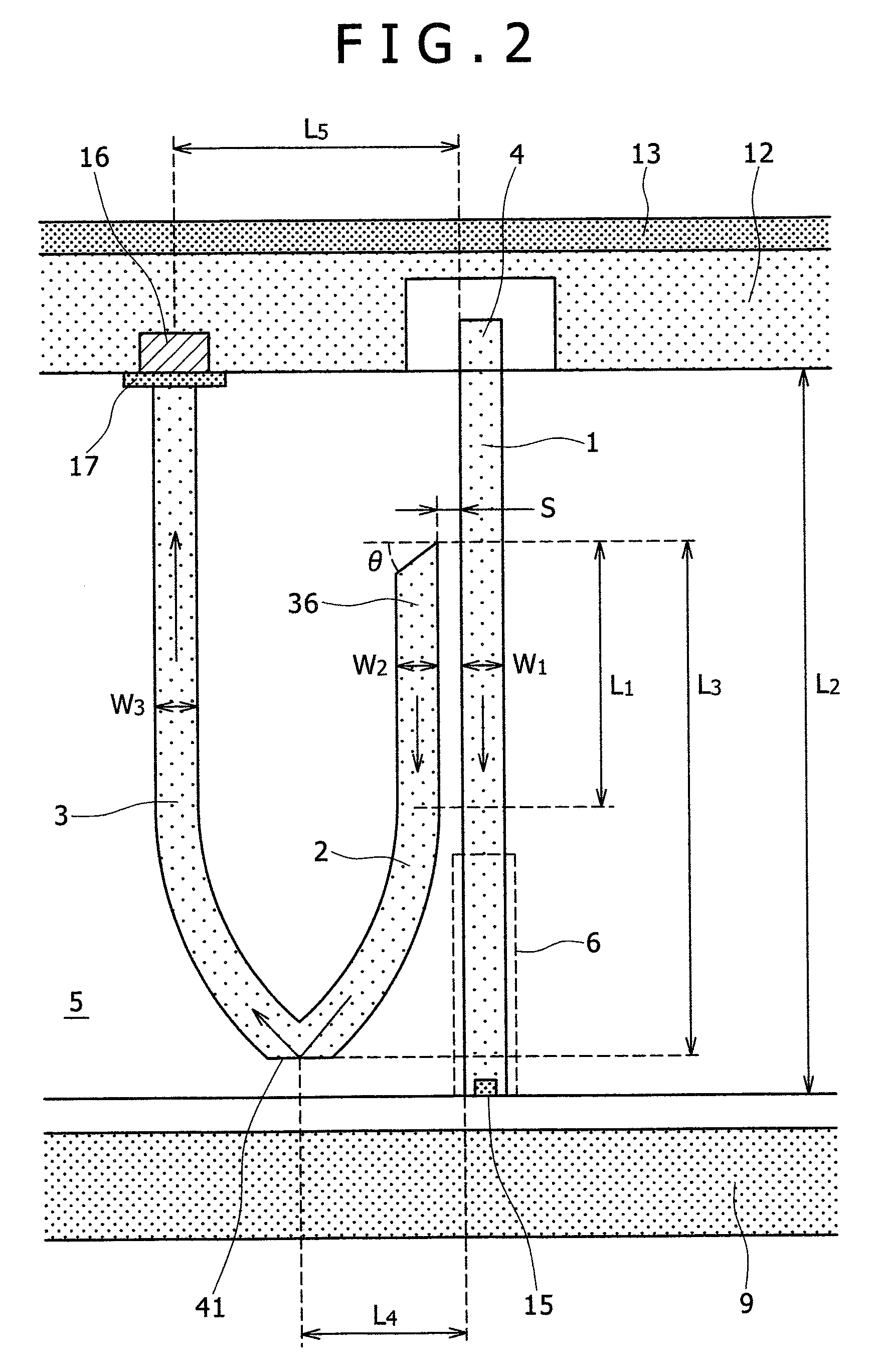
[0020]A tapered portion may be disposed at the end on the light incident side of the first waveguide for enhancing the coupling efficiency between the incident light and the waveguide. In this case, since higher order modes are excited at a portion where the width of the waveguide is enlarged to cause interference with the fundamental mode, optical power in the waveguide fluctuates. However, fluctuation of the optical power can be suppressed by constituting a feedback loop such that the second waveguide is disposed near the narrowed portion of the first waveguide situated on the side nearer to the medium, and the light coupled to the second waveguide is detected by a photodetector to make the optical power constant in the waveguide.
[0021]Instead of introducing the incident light directly to the first waveguide for guiding the light to the vicinity of the main pole, the incident light may also be guided to the second waveguide for monitoring the amount of the light. In this case, by making the width for the core of the second waveguide larger than the width for the core of the first waveguide, the entire efficiency (ratio between the energy of light at the inlet of the waveguide and the energy of the near field light) can be made larger than that in the case of introducing the incident light directly to the first waveguide. That is, in a case of coupling the incident light to the second waveguide, the coupling efficiency of the incident light to the second waveguide is increased as the diameter of the mode field of the second waveguide is nearer to the diameter for the incident light. On the other hand, the near field light generation efficiency is enhanced more as the diameter of the mode field of the first waveguide is smaller. Accordingly, the coupling efficiency of the incident light to the second waveguide is enhanced by making the width for the second waveguide larger such that the diameter of the mode field of the second waveguide approaches the diameter of the incident light. Then, in a case of transferring the light by way of the evanescent light from the second waveguide to the first waveguide of a smaller width, the light can be guided efficiently to the first waveguide of a smaller width. That is, the entire efficiency can be increased.
[0022]In a case of introducing light to the second waveguide, for improving the coupling efficiency from the second waveguide to the first waveguide, the width for the second waveguide is narrowed in a portion where the two waveguides are coupled. Alternatively, the width for the first waveguide is narrowed, or the widths for both of the first and the second waveguides are preferably narrowed. In this case, for the relation between the diameter of the mode field of the waveguide and the width for the waveguide, it is set such that the width for one of the narrowed portions is Wmin or less assuming the width where the diameter of the mode field is reduced to minimum as: Wmin. As described above, in a case of narrowing the width, the diameter of the mode field of the waveguide is enlarged in the narrowed portion and the exuding depth of the evanescent light exuding to the core surface is increased. As a result, light exudes more on the other side of the waveguide and, as a result, the coupling efficiency is improved.
[0027]According to the invention, in the thermally assisted magnetic recording head, fluctuation of the light intensity due to external disturbances such as temperature change or vibrations, or aging deterioration of the light source such as a semiconductor laser can be detected. Further, in a thermally assisted magnetic recording apparatus in which a light source such as a semiconductor laser is disposed to the outside of a flying slider and the light source and a flying slider are coupled through a waveguide or by free wave propagation, or in a thermally assisted magnetic recording apparatus in which the light source is disposed on the slider, fluctuation of the light intensity due to external disturbances such as temperature change or vibrations, or aging deterioration of the light source can be decreased and, as a result, stable recording can be attained.

Problems solved by technology

In the existent magnetic recording apparatus, when the recording density exceeds 1 Tb / in2, this results in a problem of erasing recorded information by thermal fluctuation.
However, since the magnitude of magnetic fields that can be generated from a recording head is limited, recording bits cannot be formed to the medium if the coercivity is increased excessively.
(1) Due to the degradation of an adhesive or solder that fixes the semiconductor laser or the micro lens, the position for the semiconductor laser or the micro lens is displaced during long time use to change the coupling efficiency between the waveguide and the incident light.
(2) Thermal deformation is caused to the slider or the optical element due to the heat generated from the semiconductor laser or the heat generated in the drive, to change the coupling efficiency between the waveguide and the incident light.
(3) For increasing the coupling efficiency between the waveguide and the incident light, the diameter for the light distribution in the waveguide is preferably made about equal with the spot diameter of the incident light. The diameter of the mode field means the width of the intensity distribution of the light in the waveguide. Usually, the diameter of the light spot at the emission end of the semiconductor laser is several μm. Even when this is condensed by a lens, it can only be restricted to about 1 to 2 μm due to the limit of diffraction. Accordingly, it is preferred to increase diameter of the mode field to about 1 to 2 μm. On the other hand, in the thermally assisted magnetic recording, it is preferred that the diameter of the light spot is decreased about to the same extent as the recording bit. If the diameter of the light spot is larger than the recording bit, an adjacent bit is heated to erase the recording bit thereof. For overcoming the problem of erasing the adjacent bit, a micro light spot is generated by utilizing an optical near-field generator. For example, an optical near-field generator such as a metal scatterer of a trigonal shape is disposed at the emission end of the waveguide in the slider (refer to T. Matsumoto, et al., Optics Letter, Vol. 31, P 259, (2006)). In this case, for enhancing the efficiency of generating the near-field light, it is preferred to make the spot diameter of light incident to the optical near-field generator as small as possible. That is, it is preferred to make the diameter of the mode field in the waveguide as small as possible. As a method of satisfying the requirement described above, there may be considered a method of making the width of the waveguide larger at the inlet of the waveguide, which is made gradually smaller as it approaches the optical near-field generator. In this case, since the width is large at the inlet of the waveguide, there may be a possibility that higher order propagation modes as well as fundamental mode is also excited. If the higher order modes are excited, the higher order modes and the fundamental mode cause interference in the waveguide. Then, distribution of the light intensity in the waveguide changes due to external disturbance such as temperature. As a result, the intensity of the light transmitting through a narrowed portion of the waveguide fluctuates.
As a result, the recording condition changes on every time and stable recording is no longer possible (bit error rate increase).

Method used


Image

  • Thermally assisted magnetic recording head and magnetic recording apparatus
  • Thermally assisted magnetic recording head and magnetic recording apparatus
  • Thermally assisted magnetic recording head and magnetic recording apparatus

Examples


Embodiment Construction

[0058]Preferred embodiments of the present invention are to be described with reference to the drawings.

[0059]FIGS. 3A and 3B show an entire view of a thermally assisted magnetic recording head according to the invention. FIG. 3A is a side elevational view for a flying slider and FIG. 3B shows an entire view of a suspension and a slider. A semiconductor laser 25 at a wavelength of 780 nm is utilized as a light source and the semiconductor laser 25 is placed on an arm 34 as shown in FIG. 3B. Light generated from the semiconductor laser 25 is guided by utilizing a waveguide 4 to a flying slider 5. As the waveguide 4, an optical fiber formed of an organic waveguide or glass is utilized. A coupling lens 23 is disposed between the semiconductor laser 25 and the waveguide 4 to couple the light from the semiconductor laser to the waveguide 4. The semiconductor laser and the coupling lens are fabricated in a thin package 24. The end 4a of the waveguide 4 on the side opposite to the light so...


PUM


Abstract

A second waveguide is formed near a first waveguide for guiding light to the vicinity of a main pole of a thermally assisted magnetic recording head, and a portion of light propagated through the waveguide 1 is branched to the second waveguide. The light transmitting in the second waveguide is detected by a photodetector to detect an intensity of the light propagated through the first waveguide. In the magnetic recording apparatus, an intensity of a semiconductor laser is decreased when an amount of light incident to the photodetector is large and the intensity of the semiconductor laser is increased when the amount of light incident to the photodetector is small. By constituting a feedback loop as described above, the intensity of the light propagated through the first waveguide is kept constant.

Description

CLAIM OF PRIORITY[0001]The present application claims priority from Japanese application JP 2007-042486, filed on Feb. 22, 2007, the content of which is hereby incorporated by reference into this application.BACKGROUND OF THE INVENTION[0002]1. Field of the Invention[0003]The present invention relates to a thermally-assisted magnetic recoding head and a magnetic recording apparatus.[0004]2. Description of the Related Art[0005]In recent years, a thermally assisted magnetic recording system has been proposed as a recording system for attaining a recording density of 1 Tb / in2 or more (refer to H. Saga, H. Nemoto, H. Sukeda, and M. Takahashi, Jpn. J. Appl. Phys. 38, Part 1, pp 1839 (1999)). In the existent magnetic recording apparatus, when the recording density exceeds 1 Tb / in2, this results in a problem of erasing recorded information by thermal fluctuation. In order to prevent this, it is necessary to increase the coercivity of a magnetic recoding medium. However, since the magnitude ...

Claims


Application Information

Patent Timeline
IPC IPC(8): G11B5/02
CPCG11B5/314G11B5/105G11B2005/0021G11B5/6088
Inventor MATSUMOTO, TAKUYASHIMIZU, JUNICHIRO
Owner HITACHI LTD
Learn More