Methods for the optical transmission of polarization multiplex signals

Inactive Publication Date: 2011-01-04
XIEON NETWORKS SARL
View PDF24 Cites 84 Cited by
  • Summary
  • Abstract
  • Description
  • Claims
  • Application Information

AI Technical Summary

Benefits of technology

[0014]The mutual influence is further reduced if adjacent channels have (in this instance circular) polarizations that are orthogonal in respect of each other.
[0015]Only if both optical data signals in a POLMUX channel simultaneously have an active signal (generally the logical 1 of the binary data signal), is there a resulting POLMUX signal with a different polarization from the individual modulated data signals. In the case of transmission of only one active modulated data signal respectively in a channel—the other modulated data signal corresponds to the logical zero, at which the carrier signal is suppressed—if no further measures were taken, there would be a strong mutual influence, if the modulated data signals of the other channels had the same polarization. This is advantageously prevented by rotating the polarization planes of the modulated data signals in every second channel through 45°. This reduces the “worst case” interference. However there is rather stronger mutual interference than in the optimum instance, in which the original modulated signals of adjacent channels were polarized orthogonally in respect of each other; however a reduction in the disruptive influence in worst case instances is more important.
[0016]It is also advantageous that in a first channel a first optical data signal and a second optical data signal without a phase difference between their carrier signals are combined to form a polarization multiplex signal and that in a second channel the carrier signal of a second optical data signal is phase-shifted by 180° in respect of the carrier signal of its first optical data signal and combined with a first optical data signal to for

Problems solved by technology

However the data transmission ranges in transmission systems with polarization multiplexing are seriously restricted by non-linear interference effects.
Because of the constantly alternating bit sequences this results in a noise-type change in the polarization state of

Method used


Image

  • Methods for the optical transmission of polarization multiplex signals
  • Methods for the optical transmission of polarization multiplex signals
  • Methods for the optical transmission of polarization multiplex signals

Examples


Embodiment Construction

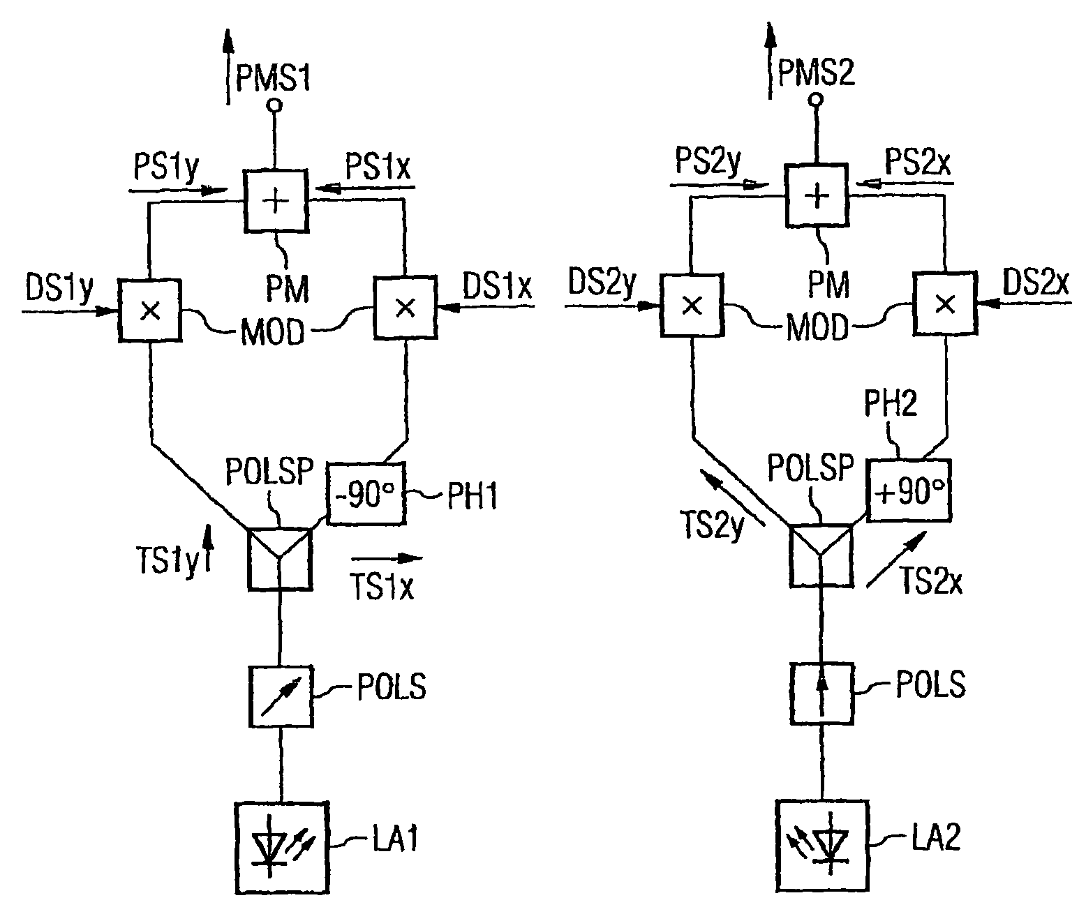
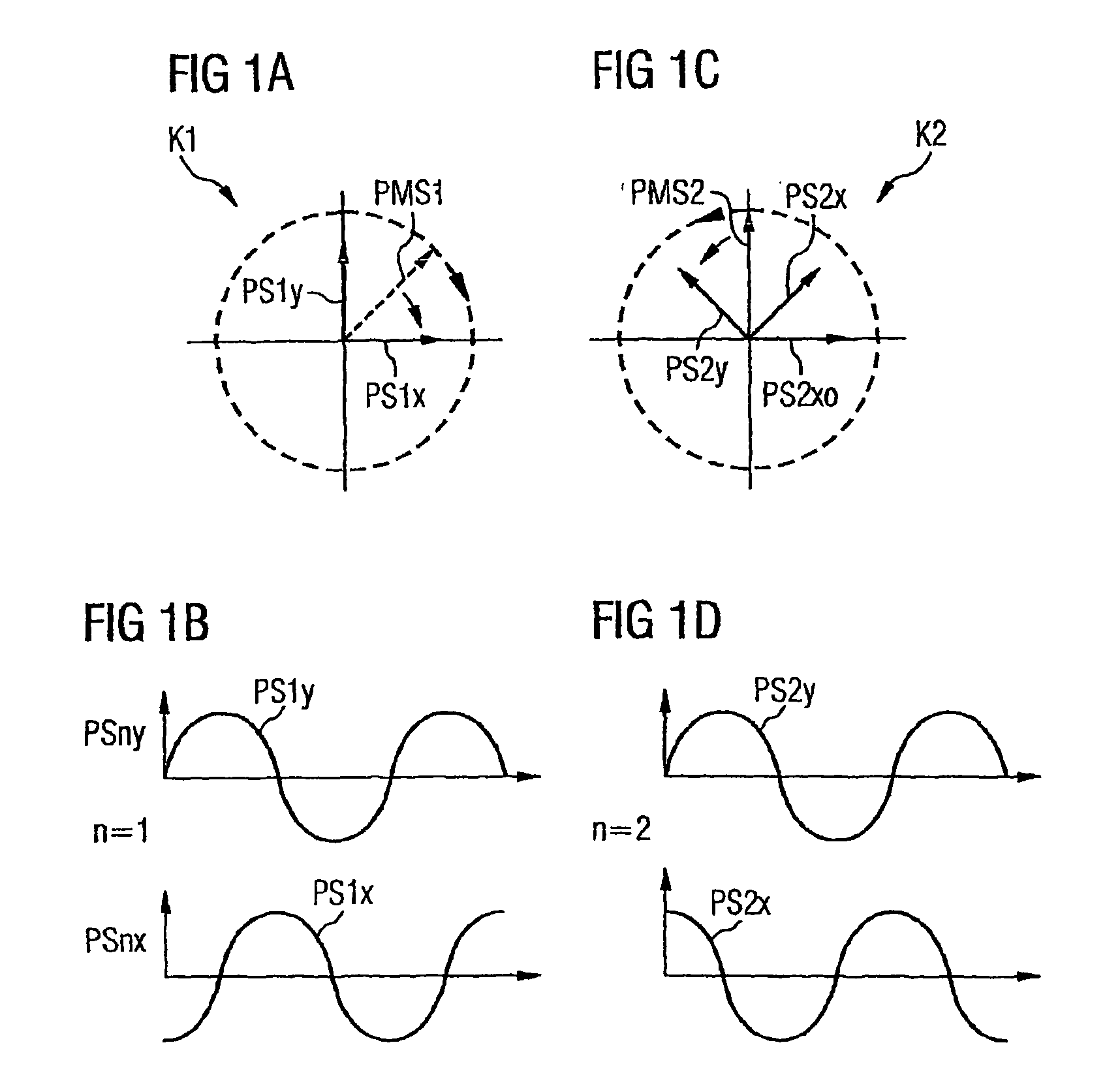
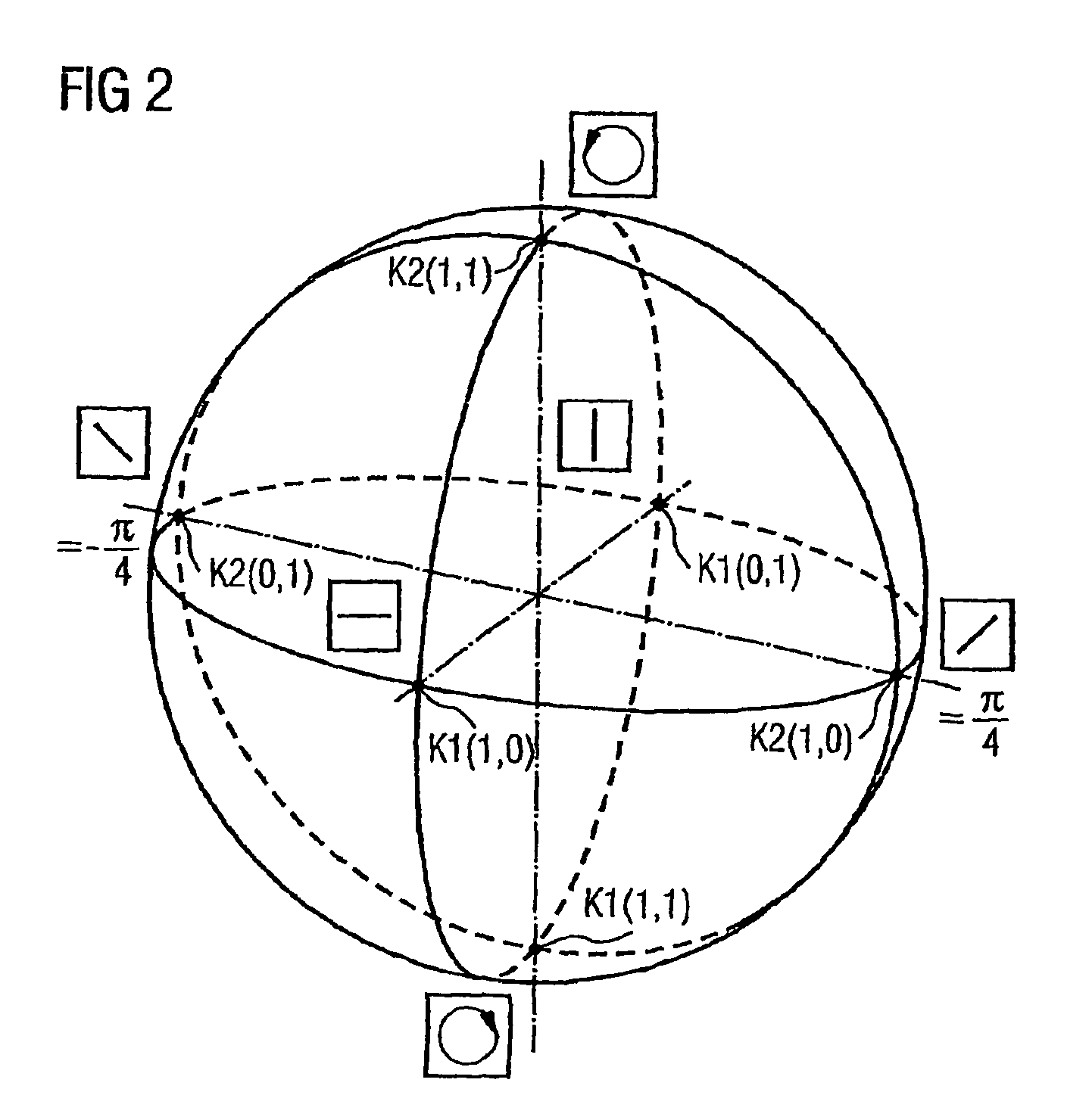
[0032]FIG. 1 shows the polarization and phase relationship of two POLMUX signals in adjacent POLMUX channels K1 and K2. The invention is to be described with reference to two adjacent channels, with the same resulting for further channels. Two optical data signals modulated with the logical 1 PS1x and PS1y are transmitted in the first POLMUX channel K1. The snapshot shows the amplitudes of the E-field vectors. The transmission direction in one fiber is perpendicular to the plane of the drawing. The amplitude-modulated data signal PS1x is polarized horizontally here and the amplitude-modulated data signal PS1y is polarized vertically. Both signals also have a mutual phase shift of ±90° between their optical carrier signals (in this instance PS1x −90° for example, FIG. 1b), so that a resulting POLMUX signal PMS1 has a right-hand circular polarization (dashed). The POLMUX signals in further channels of the WDM system are also polarized in a circular manner; as they have different wavel...


PUM


Abstract

In order to reduce mutual interferences between POLMUX and signals, the signals are transmitted with differed to each other carrying signals, thereby making it possible to obtain the circular polarization of each resulting POLMUX signal. Each second POLMUX signal is transmissible with an opposite circular polarization. In order to reduce also interferences when only one modulated data signal is transmitted through a POLMUX channel, a polarization plane of modulated data signals of each second POLMUX channel is turned at 45°. In a variant, polarization multiplex signals are produces and the resulting polarizations thereof in adjacent channels are perpendicular to each other.

Description

CROSS REFERENCE TO RELATED APPLICATIONS[0001]This application is the US National Stage of International Application No. PCT / EP2006 / 050429, filed Jan. 25, 2006 and claims the benefit thereof. The International Application claims the benefits of German application No. 102005003679.1 DE filed Jan. 26, 2005 and German application No. 102005003681.3 DE filed Jan. 26, 2005, all of the applications are incorporated by reference herein in their entirety.FIELD OF INVENTION[0002]The invention relates to methods for the transmission of polarization multiplex signals combined to form a wavelength division multiplex signal.BACKGROUND OF THE INVENTION[0003]The transmission of data in transmission systems with multiplex technology allows a plurality of users to use a transmission medium simultaneously, thereby significantly extending transmission capacity. With the optical wavelength division multiplexing method (abbreviated to WDM) N modulated optical signals in NRZ format (hereafter also referre...

Claims


Application Information

Patent Timeline
IPC IPC(8): H04J14/06H04J14/04H04J14/00H04J14/02G01C19/72G02B6/28H04J11/00
CPCH04J14/02H04J14/06
Inventor HECKER, NANCYPAETSCH, WERNERVAN DEN BORNE, DIRK
Owner XIEON NETWORKS SARL
Why Eureka
Try Eureka