Large-mode-area optical fibers with reduced bend distortion

a technology of optical fibers and bend distortion, applied in the field of optical fibers, can solve the problems of reducing the effective transverse mode area of lma optical fibers, reducing the interaction of the fundamental transverse mode with the gain region in the gain-producing lma fiber, and also significantly reducing the effective transverse mode area. , to achieve the effect of reducing the effective transverse mode area, reducing the interaction, and improving performan

Active Publication Date: 2009-03-05
FURAKAWA ELECTRIC NORTH AMERICA INC
View PDF14 Cites 102 Cited by
  • Summary
  • Abstract
  • Description
  • Claims
  • Application Information

AI Technical Summary

Benefits of technology

[0013]My analysis of the impact of bend distortion demonstrates that it not only reduces effective transverse mode area in LMA optical fibers but also significantly degrades the interaction of the fundamental transverse mode with the gain region in gain-producing LMA fibers. This interaction is quantified using conventional gain-overlap integrals and also using a measure of energy extraction from the gain by the signal mode. A fiber having a graded-index core, designed according to my distortion-resistant strategy, is shown herein to have far better performance according to these gain-interaction metrics and, in addition, according to loss and mode-coupling indicators.

Problems solved by technology

My analysis of the impact of bend distortion demonstrates that it not only reduces effective transverse mode area in LMA optical fibers but also significantly degrades the interaction of the fundamental transverse mode with the gain region in gain-producing LMA fibers.

Method used


Image

  • Large-mode-area optical fibers with reduced bend distortion
  • Large-mode-area optical fibers with reduced bend distortion
  • Large-mode-area optical fibers with reduced bend distortion

Examples


Embodiment Construction

Optical Fibers—General Considerations

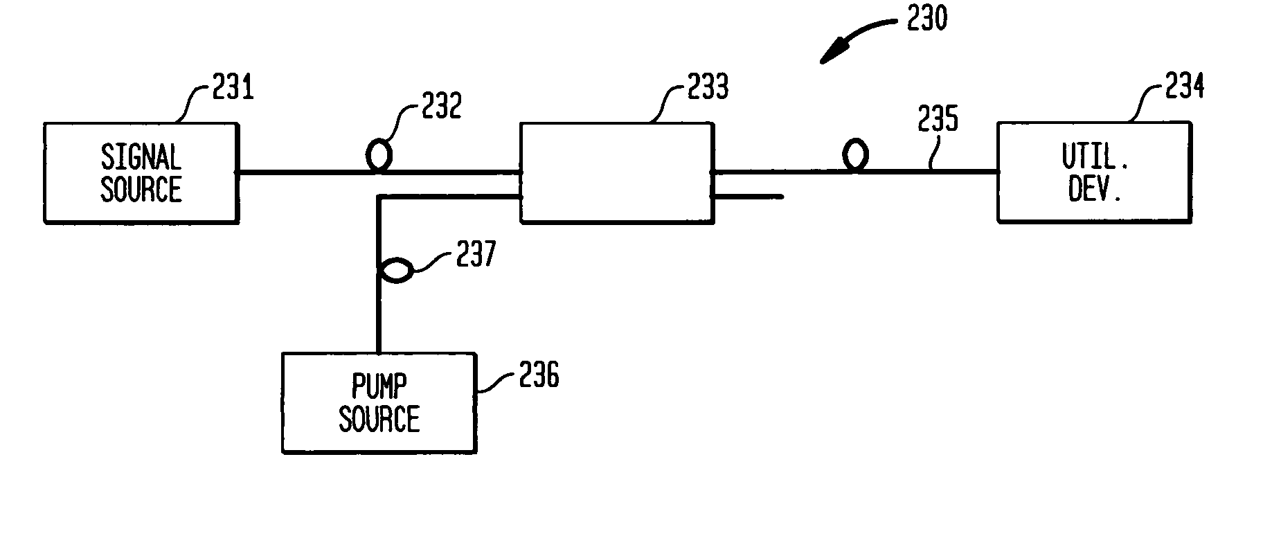
[0044]Turning now to FIG. 9C, an optical fiber 90 comprises a core region 91 having a longitudinal axis 93 and a cladding region 92 surrounding the core region. The core region 91 and cladding region 92 are configured to support and guide the propagation of signal light in the core region in the direction of the axis. To this end, the index of the core region 91 (ncore=nc) is greater than that of the cladding region 92 (nclad). Preferably the core and cladding regions are configured to propagate light preferentially in the fundamental transverse mode at the center wavelength of the signal light. To this end, higher order modes (HOMs) may be suppressed by techniques well-known in the art; for example, by appropriate use of high bend loss, gain selectivity, or resonant coupling HOMs to a high-index ring. The latter is described by me in copending patent application Ser. No. 11 / 818,780 (Fini 5), which was filed on Jun. 15, 2007 and is entitled “Bend...


PUM

PropertyMeasurementUnit
effective mode areaaaaaaaaaaa
core diameteraaaaaaaaaa
lengthsaaaaaaaaaa

Abstract

In a LMA optical fiber the index of the core region is graded (i.e., as viewed in a radial cross-section) and has a grading depth of Δng, as measured from a central maximum at or near the axis to a lower level that is not greater than the central maximum and not less than the index of the cladding region. When the fiber is to be bent at a bend radius, the grading depth, the radius of the core region, and the difference between the central maximum index and the cladding region index are configured to reduce bend distortion. They may also advantageously be configured to maximize the effective mode-field area of the fundamental mode, suppress higher order modes, and reduce bend loss. In a preferred embodiment, the core region includes a centralized gain region, which in turn includes a dark region that is no more than 30% of the area of the gain region. Also described is a method of making such LMA fibers.

Description

CROSS-REFERENCE TO RELATED APPLICATIONS[0001]This application claims priority from provisional application Ser. No. 60 / 893,048, which was filed on Mar. 5, 2007 and is entitled “Large-Mode-Area Fibers.”[0002]This application is also a continuation-in-part of application Ser. No. 11 / 319,121 (Fini 2), which was filed on Dec. 27, 2005 and is entitled “Optical Fiber with Specialized Index Profile to Compensate for Bend-Induced Distortion.”GOVERNMENT CONTRACT[0003]This invention was made with Government support under the Advanced Technology Program of the National Institute of Standards and Technology, Award No. 70NANB41H3035. The Government has certain rights in this invention.BACKGROUND OF THE INVENTION[0004]1. Field of the Invention[0005]This invention relates to optical fibers and, more particularly, to large-mode-area (LMA) optical fibers with reduced bend distortion.[0006]2. Discussion of the Related Art[0007]The ever increasing demand for higher optical power output from fiber ampl...

Claims


Application Information

Patent Timeline
Patent Type & Authority Applications(United States)
IPC IPC(8): H01S3/067G02B6/028G06F17/50C03B37/00
CPCG02B6/02009H01S3/06708G02B6/0281
Inventor FINI, JOHN MICHAEL
Owner FURAKAWA ELECTRIC NORTH AMERICA INC
Why Eureka
Try Eureka