Ionizer and method for gas-cluster ion-beam formation

a technology of ionizer and gascluster, which is applied in the field of ionizing gascluster jets to form, can solve the problems of large impact effects of large clusters, corrosive gas components inside the ionizer, and ionizers are evolving, and can be easily attacked by reactive and corrosive gases, so as to achieve high ionization efficiency and prolong filament life , the effect of high throughput processing of workpieces

Active Publication Date: 2007-02-06
TEL EPION
View PDF16 Cites 94 Cited by
  • Summary
  • Abstract
  • Description
  • Claims
  • Application Information

AI Technical Summary

Benefits of technology

[0008]It is therefore an object of this invention to provide an ionizer and methods for generating a GCIB with high ionization efficiency for high throughput processing of workpieces.
[0009]It is a further object of this invention to provide a GCIB ionizer having an extended filament lifetime when operating with gas-clusters containing reactive gas molecules.
[0010]It is another object of this invention to provide a GCIB ionizer that generates lowered levels of contaminants even when operated in the presence of gas-clusters containing reactive gas molecules, especially for metallic contaminants.
[0011]An ionizer for ionizing a gas-cluster jet to form a gas-cluster ion-beam has a very transparent structure to facilitate high gas conductivity and to minimize internal pressure during ionization. A plasma source provides copious electrons at relatively low energies. The plasma source has a thermionic filament that is isolated from the gas-cluster ionization region to reduce interaction between the thermionic filament and corrosive gas components that may be evolved from the gas-clusters being ionized. To a substantial degree, the design permits substitution of non-metallic construction materials to produce lowered contribution to particulate and metal contamination of the workpieces processed in a GCIB processing apparatus. Most components exposed to the gas-cluster jet and its evolution products are constructed from high purity graphite, and though a hot metallic filament is used, it interacts little with any reactive gas-cluster jet evolution products. This results in extended filament operating life, and reduced contribution of contaminants from the metal filament.

Problems solved by technology

Consequently, the impact effects of large clusters are substantial, but are limited to a very shallow surface region.
Due to yield considerations, such applications typically require that processing steps contribute only very low levels of contamination.
These reactive gases pose a problem for gas-cluster ionizer design for semiconductor processing because of their corrosive nature.
When gas-clusters comprising NF3 and O2 are bombarded by electrons during ionization to form gas-cluster ions, there is a certain amount of evaporation of the gas-clusters that results, evolving corrosive gas components inside the ionizer.
Since thermionic filaments used to generate thermoelectrons for ionization operate at high temperatures, they are susceptible to attack by the reactive and corrosive gases that are evolved.
It shortens the operational lifetime of the filaments in the ionizers, and it results in the generation of small particles and molecules or ions of potential contaminants that can interfere with the yield of semiconductor processes.
In a GCIB processing tool for application in the field of semiconductor processing, or in any field of application requiring low levels of contamination, such generation of contaminants is detrimental to the GCIB processing because such contaminants inevitably transport from the ionizer to the surfaces of the workpieces being processed.
An undesirable side effect of this expedient is that the energies of the impact ionization ionizing electrons are higher than desirable, often several hundred electron volts.
In some GCIB processing applications, large quantities of highly ionized (ionization state above 3 or 4) gas-cluster ions are considered detrimental to the process.

Method used


Image

  • Ionizer and method for gas-cluster ion-beam formation
  • Ionizer and method for gas-cluster ion-beam formation
  • Ionizer and method for gas-cluster ion-beam formation

Examples


Embodiment Construction

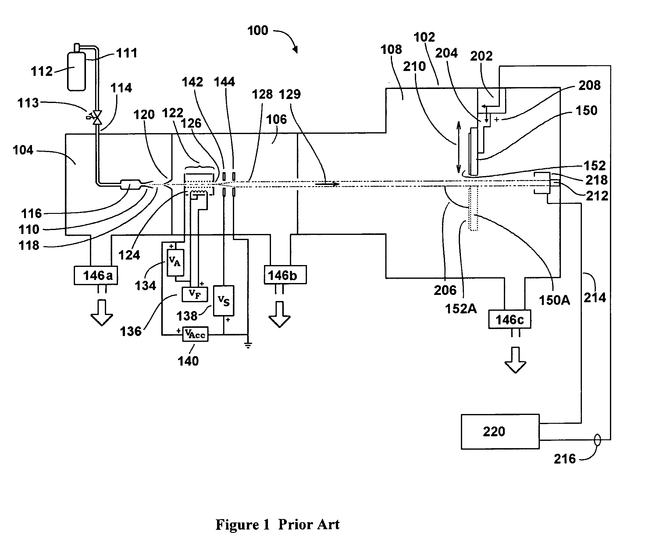
[0027]FIG. 1 shows a configuration for a GCIB processing apparatus 100 of a form known in prior art, and which may be described as follows: a vacuum vessel 102 is divided into three communicating chambers, a source chamber 104, an ionization / acceleration chamber 106, and a processing chamber 108. The three chambers are evacuated to suitable operating pressures by vacuum pumping systems 146a, 146b, and 146c, respectively. A condensable source gas 112 (for example argon or O2) stored in a gas storage cylinder 111 is admitted under pressure through gas metering valve 113 and gas feed tube 114 into stagnation chamber 116 and is ejected into the substantially lower pressure vacuum through a properly shaped nozzle 110. A supersonic gas jet 118 results. Cooling, which results from the expansion in the jet, causes a portion of the gas jet 118 to condense into clusters, each consisting of from several to several thousand weakly bound atoms or molecules. A gas skimmer aperture 120 partially s...


PUM


Abstract

An ionizer for forming a gas-cluster ion beam is disclosed including inlet and outlet ends partially defining an ionization region traversed by a gas-cluster jet and one or more plasma electron source(s) for providing electrons to the ionizing region for ionizing at least a portion of the gas-clusters to form a gas-cluster ion beam. One or more sets of substantially linear rod electrodes may be disposed substantially parallel to and in one or more corresponding partial, substantially cylindrical pattern(s) about the gas-cluster jet axis, wherein some sets are arranged in substantially concentric patterns with differing radii. In certain embodiments, the ionizer includes one or more substantially linear thermionic filaments disposed substantially parallel to the gas-cluster jet axis, heating means, electrical biasing means to judiciously bias sets of the linear rod electrodes with respect to the thermionic filaments to achieve electron repulsion.

Description

CROSS REFERENCE TO RELATED PATENT APPLICATIONS[0001]This Application claims priority of U.S. Provisional application Ser. No. 60 / 621,913 entitled “Ionizer and Method for Gas-Cluster Ion-Beam Formation”, filed Oct. 25, 2004, the contents of which are incorporated herein by reference.FIELD OF THE INVENTION[0002]The present invention relates generally to methods and apparatus for ionizing a gas-cluster jet to form a gas-cluster ion beam (GCIB) for processing the surface of a workpiece and, more particularly, to forming a high current GCIB for workpiece processing with reduced workpiece metals contamination.BACKGROUND OF THE INVENTION[0003]The use of a gas-cluster ion beam (GCIB) for etching, cleaning, and smoothing surfaces is known in the art (see, for example, U.S. Pat. No. 5,814,194, Deguchi et al., incorporated herein by reference). GCIBs have also been employed for assisting the deposition of films from vaporized carbonaceous materials (see, for example, U.S. Pat. No. 6,416,820, Y...

Claims


Application Information

Patent Timeline
Patent Type & Authority Patents(United States)
IPC IPC(8): H01J27/02H01J27/00H01J49/00
CPCH01J27/026H01J27/08H01J37/3053H01J37/08H01J2237/0812H01J2237/0041
Inventor MACK, MICHAEL E.
Owner TEL EPION
Why Eureka
Try Eureka