Method for treating wastewater in a membrane bioreactor to produce a low phosphorus effluent

a bioreactor and wastewater technology, applied in water/sewage multi-stage treatment, other chemical processes, separation processes, etc., can solve the problems of insufficient precipitation of released phosphorous to inhibit downstream biological processes, and achieve low phosphorous output, promote robust nutrient uptake, and minimize space requirements and attendant costs

Inactive Publication Date: 2005-09-20
CH2M HILL
View PDF47 Cites 96 Cited by
  • Summary
  • Abstract
  • Description
  • Claims
  • Application Information

AI Technical Summary

Benefits of technology

[0009]The method of the present invention allows for obtaining low phosphorous output by a combined biological treatment process and chemical phosphorous removal. Surprisingly, recycle of return activated sludge including residuals of the phosphorous precipitating chemical does not cause sufficient precipitation of released phosphorous to inhibit the downstream biological processes. The anaerobic zone in essence functions as a phosphorous buffer to assure a supply of phosphorous for downstream biological processes during simultaneous chemical removal of phosphorous in the downstream aerobic zone. Thus, the method allows for chemical phosphorous removal within a conventional biological treatment process including an anaerobic zone without inhibiting and still promoting robust nutrient uptake in the downstream biological zones. In addition to easing the need to provide precise amounts of phosphorous removal agents in the downstream aerobic zone, the method eliminates the need for side stream phosphorous removal processes or subsequent downstream phosphorous removal and clarification, thus minimizing space requirements and attendant cost.

Problems solved by technology

Surprisingly, recycle of return activated sludge including residuals of the phosphorous precipitating chemical does not cause sufficient precipitation of released phosphorous to inhibit the downstream biological processes.

Method used


Image

  • Method for treating wastewater in a membrane bioreactor to produce a low phosphorus effluent
  • Method for treating wastewater in a membrane bioreactor to produce a low phosphorus effluent
  • Method for treating wastewater in a membrane bioreactor to produce a low phosphorus effluent

Examples


example

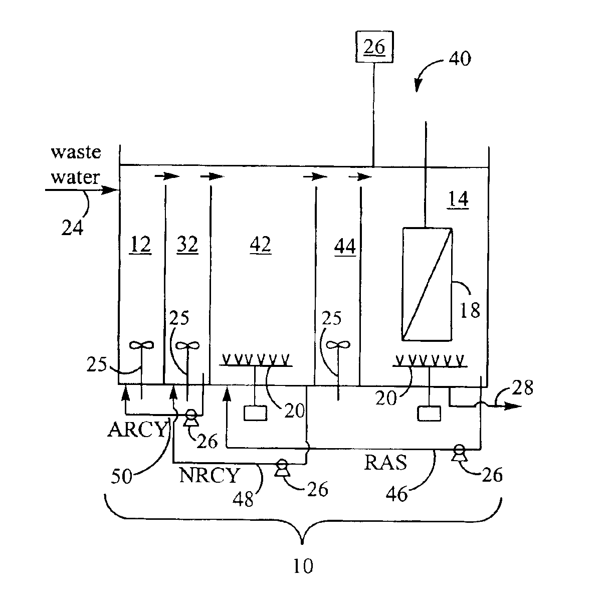
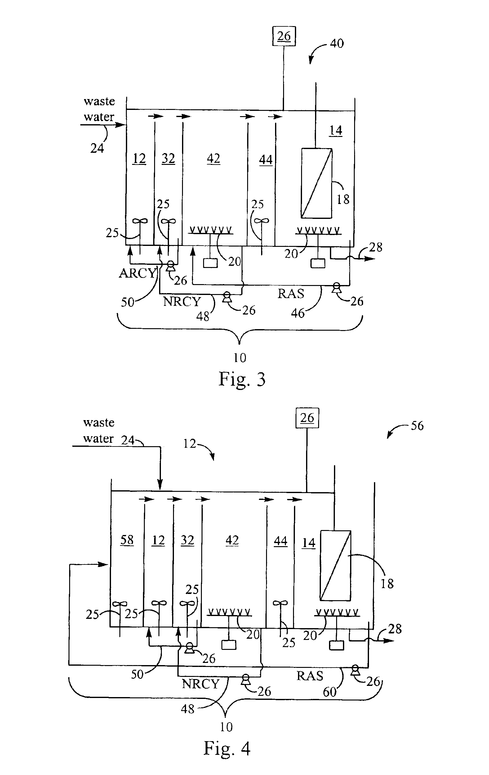
[0020]A pilot testing program was conducted to test the nutrient removal capability of the third embodiment of the membrane bioreactor (“MBR”) and method for treating wastewater described with reference to FIG. 3 above. The pilot testing program included a number of objectives. The overall objective of the program was to determine whether the MBR could achieve the effluent limitation goals shown in Table 1.

[0021]

TABLE 1Treatment GoalsParameterTreatment GoalsBiochemical Oxygen Demand (BOD), mg / LNot applicable (NA)Total Suspended Solids (TSS), mg / L1Chemical Oxygen Demand (COD), mg / L10.0aTotal Nitrogen (TN), mg / L3.0-8.0Total Phosphorus (TP), mg / L0.1Turbidity0.5 NTU(Nephelometric Turbidity Units, NTU)Coliform (per 100 mL)aCOD limit to be achieved through the post-treatment of MBR effluent with activated carbon.

[0022]The wastewater used for the pilot testing program consisted of municipal sewage from a community. The wastewater sources were mostly domestic in nature (i.e., few industria...


PUM

PropertyMeasurementUnit
concentrationsaaaaaaaaaa
concentrationaaaaaaaaaa
effluent CODaaaaaaaaaa

Abstract

Removal of biological nutrients from a wastewater yielding a low phosphorous (e.g., less than 0.25 mg / L) output includes providing a serial multistage bioreactor containing activated sludge having in hydraulic series an anaerobic zone and a downstream aerobic zone, with each zone having an upstream inlet and a downstream outlet. The wastewater is provided to the anaerobic zone inlet. A quantity of chemical sufficient to precipitate soluble and particulate phosphorous is added to the downstream aerobic zone in an amount sufficient to yield a low phosphorous output. Treated water is separated from the activated sludge and precipitated phosphorous and a return activated sludge separated from the treated water is recycled to the anaerobic zone.

Description

TECHNICAL FIELD[0001]The present invention is directed toward wastewater treatment processes, and more particularly toward an activated sludge treatment process using a membrane bioreactor (“MBR”) and using biological and chemical phosphorus removal adapted to prevent phosphorus limiting conditions in the activated sludge treatment process.BACKGROUND ART[0002]Biological treatment processes for the removal of biological nutrients such as biological oxygen demand (“BOD”), nitrates and phosphates are well known. A typical biological treatment process is an activated sludge process in which the wastewater is aerated and agitated with an activated sludge and then purged of a variety of microorganisms. Often this aerobic stage is combined with an anaerobic stage, i.e., a stage operated in the absence of induced oxygen, either soluble or derived from nitrites or nitrates (NOx) and an anoxic stage, i.e., where oxygen is absent but nitrites or nitrates are present. Phosphorus removal is acco...

Claims


Application Information

Patent Timeline
Patent Type & Authority Patents(United States)
IPC IPC(8): C02F3/30C02F3/12
CPCC02F3/1215C02F3/1273C02F3/302Y10S210/906Y02W10/10
Inventor DAIGGER, GLEN T.FLEISCHER, EDWIN J.WOLLMANN, ALBERT M.
Owner CH2M HILL
Why Eureka
Try Eureka