Internal cooling system with insert forming nearwall cooling channels in an aft cooling cavity of a gas turbine airfoil including heat dissipating ribs

a gas turbine airfoil and cooling cavity technology, applied in the direction of engine fuction, machine/engine, stators, etc., can solve the problems of consuming cooling air pressure, reducing cooling effectiveness, and less efficient use of cooling air, so as to reduce localized hot spot outer wall temperature, increase surface area, and improve cooling

Inactive Publication Date: 2018-02-15
SIEMENS AG
View PDF3 Cites 7 Cited by
  • Summary
  • Abstract
  • Description
  • Claims
  • Application Information

AI Technical Summary

Benefits of technology

[0004]An airfoil for a gas turbine engine in which the airfoil includes an internal cooling system with one or more internal cavities having an insert contained within an aft cooling cavity to form nearwall cooling channels having enhanced flow patterns is disclosed. The flow of cooling fluids in the nearwall cooling channels may be controlled via a plurality of cooling fluid flow controllers extending from the outer wall forming the generally hollow elongated airfoil. In addition, heat may be extracted in the midchord region via one or more heat dissipating ribs extending partially between an inner surface of the suction side and the insert. In at least one embodiment, the heat dissipating ribs may extend in a generally chordwise direction and be positioned from an inner diameter of the airfoil to an outer diameter of the airfoil between the cooling fluid flow controllers and a rib separating a forward cooling cavity from the aft cooling cavity. The heat dissipating ribs have been shown to increase the surface area by at least 60 percent, reduce localized hot spot outer wall temperature by up to 60 degrees Celsius while having a negligible impact on mass flow rate.

Problems solved by technology

The cross flow can bend the impinging jets away from the impingement target surface and reduce the cooling effectiveness.
However, the greater the number of film cooling holes, the less efficient usage of cooling air is.
The impingement holes consume cooling air pressure and often pose a problem at the leading edge, where showerhead holes experience high stagnation gas pressure on the external surface.

Method used


Image

  • Internal cooling system with insert forming nearwall cooling channels in an aft cooling cavity of a gas turbine airfoil including heat dissipating ribs
  • Internal cooling system with insert forming nearwall cooling channels in an aft cooling cavity of a gas turbine airfoil including heat dissipating ribs
  • Internal cooling system with insert forming nearwall cooling channels in an aft cooling cavity of a gas turbine airfoil including heat dissipating ribs

Examples


Embodiment Construction

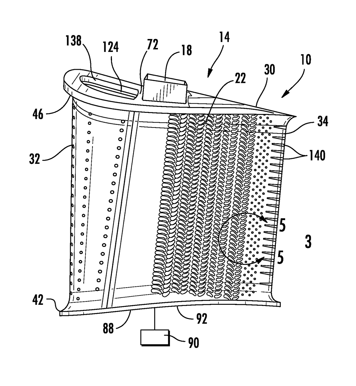
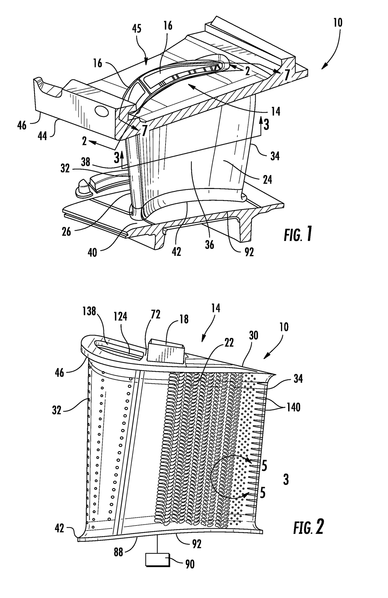
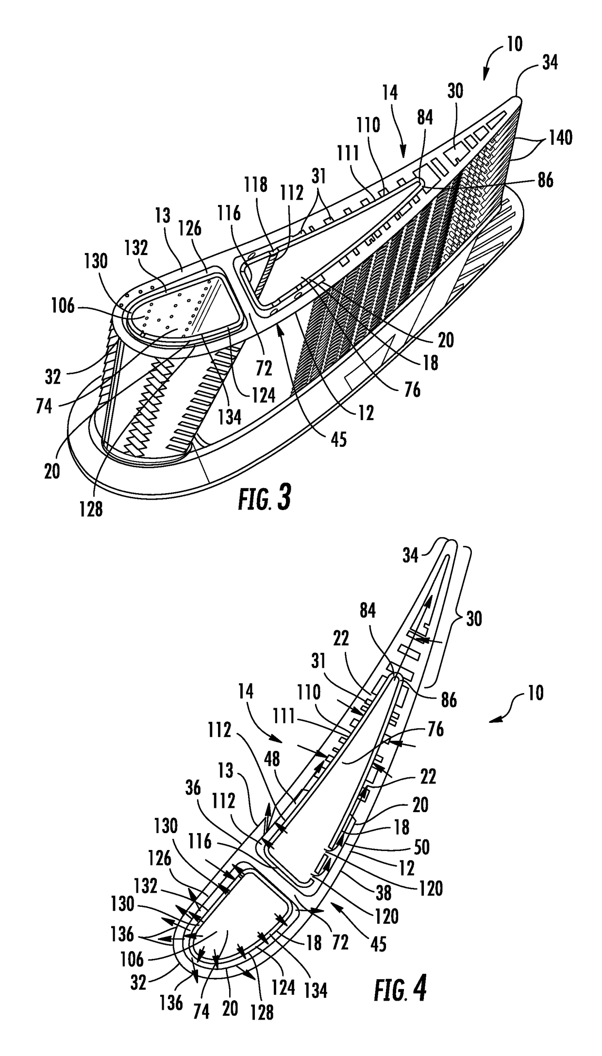
[0036]As shown in FIGS. 1-19, an airfoil 10 for a gas turbine engine in which the airfoil 10 includes an internal cooling system 14 with one or more internal cavities 16 having an insert 18 contained within an aft cooling cavity 76 to form nearwall cooling channels 20 having enhanced flow patterns is disclosed. The flow of cooling fluids in the nearwall cooling channels 20 may be controlled via a plurality of cooling fluid flow controllers 22 extending from the outer wall 24 forming the generally hollow elongated airfoil 26. In addition, heat may be extracted in the midchord region 150 via one or more heat dissipating ribs 152 extending partially between an inner surface 144 of the suction side 38 and the insert 18. In at least one embodiment, the heat dissipating ribs 152 may extend in a generally chordwise direction and be positioned from an inner diameter 92 of the airfoil 26 to an outer diameter 98 of the insert 18 between the cooling fluid flow controllers 22 and a rib 72 separ...


PUM


Abstract

An airfoil (10) for a gas turbine engine in which the airfoil (10) includes an internal cooling system (14) with one or more internal cavities (16) having an insert (18) contained within an aft cooling cavity (76) to form nearwall cooling channels having enhanced flow patterns is disclosed. The flow of cooling fluids in the nearwall cooling channels (20) may be controlled via a plurality of cooling fluid flow controllers (22) extending from the outer wall (12) forming the generally hollow elongated airfoil (26). In addition, heat may be extracted in the midchord region (150) via one or more heat dissipating ribs (152) extending partially between an inner surface (144) of the suction side (38) and the insert (18). In at least one embodiment, the heat dissipating ribs (152) may extend in a generally chordwise direction and be positioned from an inner diameter (92) to an outer diameter (98) of the airfoil (10) between the cooling fluid flow controllers (22) and a rib (72) separating forward and aft cooling cavities (74, 76).

Description

FIELD OF THE INVENTION[0001]This invention is directed generally to gas turbine engines, and more particularly to internal cooling systems for airfoils in gas turbine engines.BACKGROUND[0002]Typically, gas turbine engines include a compressor for compressing air, a combustor for mixing the compressed air with fuel and igniting the mixture, and a turbine blade assembly for producing power. Combustors often operate at high temperatures that may exceed 2,500 degrees Fahrenheit. Typical turbine combustor configurations expose turbine vane and blade assemblies to high temperatures. As a result, turbine vanes and blades must be made of materials capable of withstanding such high temperatures, or must include cooling features to enable the component to survive in an environment which exceeds the capability of the material. Turbine engines typically include a plurality of rows of stationary turbine vanes extending radially inward from a shell and include a plurality of rows of rotatable tur...

Claims


Application Information

Patent Timeline
Patent Type & Authority Applications(United States)
IPC IPC(8): F01D5/18F01D9/02
CPCF01D5/187F01D9/02F05B2260/2241F05B2250/183F01D5/189F01D9/041F05D2240/127F05D2260/22141F05D2260/201
Inventor LEE, CHING-PANGUM, JAE Y.PU, ZHENGXIANGMYERS, CALEB
Owner SIEMENS AG
Why Eureka
Try Eureka