Strip casting apparatus with improved side dam

a strip casting and side dam technology, applied in the field of continuous casting of thin metal strips, can solve the problems of strip surface reheating, strip breaking, side dam wear,

Inactive Publication Date: 2010-06-03
NUCOR CORP
View PDF7 Cites 3 Cited by
  • Summary
  • Abstract
  • Description
  • Claims
  • Application Information

AI Technical Summary

Benefits of technology

[0004]Further, the twin roll caster may be capable of continuously producing cast strip from molten steel through a sequence of ladles. Pouring the molten metal from the ladle into a smaller vessel before flowing through the metal delivery nozzle enables the exchange of an empty ladle with a full ladle without disrupting the production of cast strip.
[0005]During operation, the metal flow rate and molten metal temperature in the area where the side dams, casting rolls and meniscus of the casting pool intersect, i.e. the “triple point” area or region, is controlled. Notably, the distance between the side dams and the ends of the delivery nozzles nearest the side dams should be controlled and maintained to prevent the formation of unwanted steels skulls either on the side dam or delivery nozzle.

Problems solved by technology

This movement affects the side dam force and thus side dam wear.
When these skulls drop into the roll nip, they cause the two solidifying shells at the casting roll nip to separate and “swallow” additional liquid steel between the shells causing the strip surface to reheat and causing the strip to break thus disrupting the continuous production of coiled strip.
Snake eggs also apply resistive forces against the side dam in addition to the forces generated by the ferrostatic head in the cast pool and can thus cause the side dam to lift from the casting roll edge resulting in the leakage of steel between the side dam and the casting roll necessitating termination of the casting sequence.
Additionally, snake eggs passing through the nip between the casting rolls can cause lateral movement of the casting rolls and also cause movement in the side dams.
To resist the increased forces generated by the snake eggs and the stiction of the side dam apply cylinders, the side dams are typically applied to the casting rolls with higher forces, thus increasing side dam wear.

Method used


Image

  • Strip casting apparatus with improved side dam
  • Strip casting apparatus with improved side dam
  • Strip casting apparatus with improved side dam

Examples


Embodiment Construction

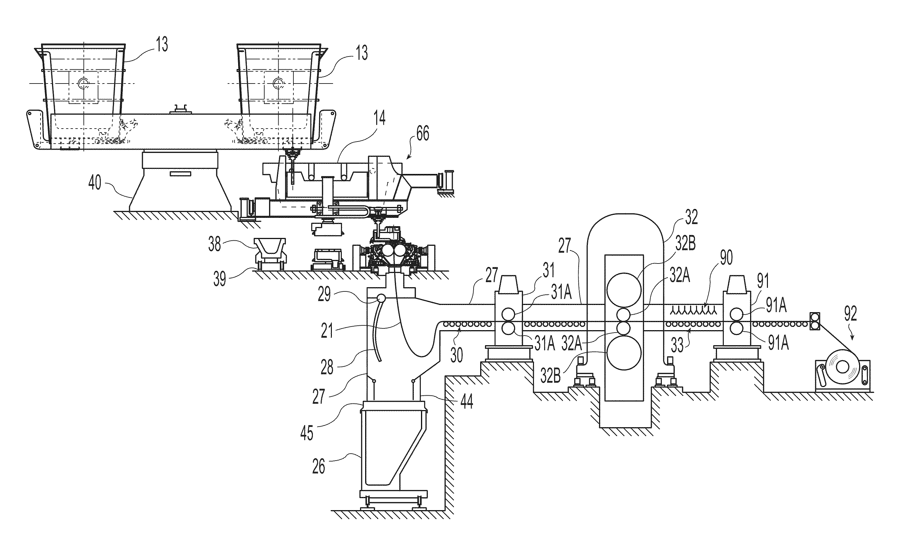
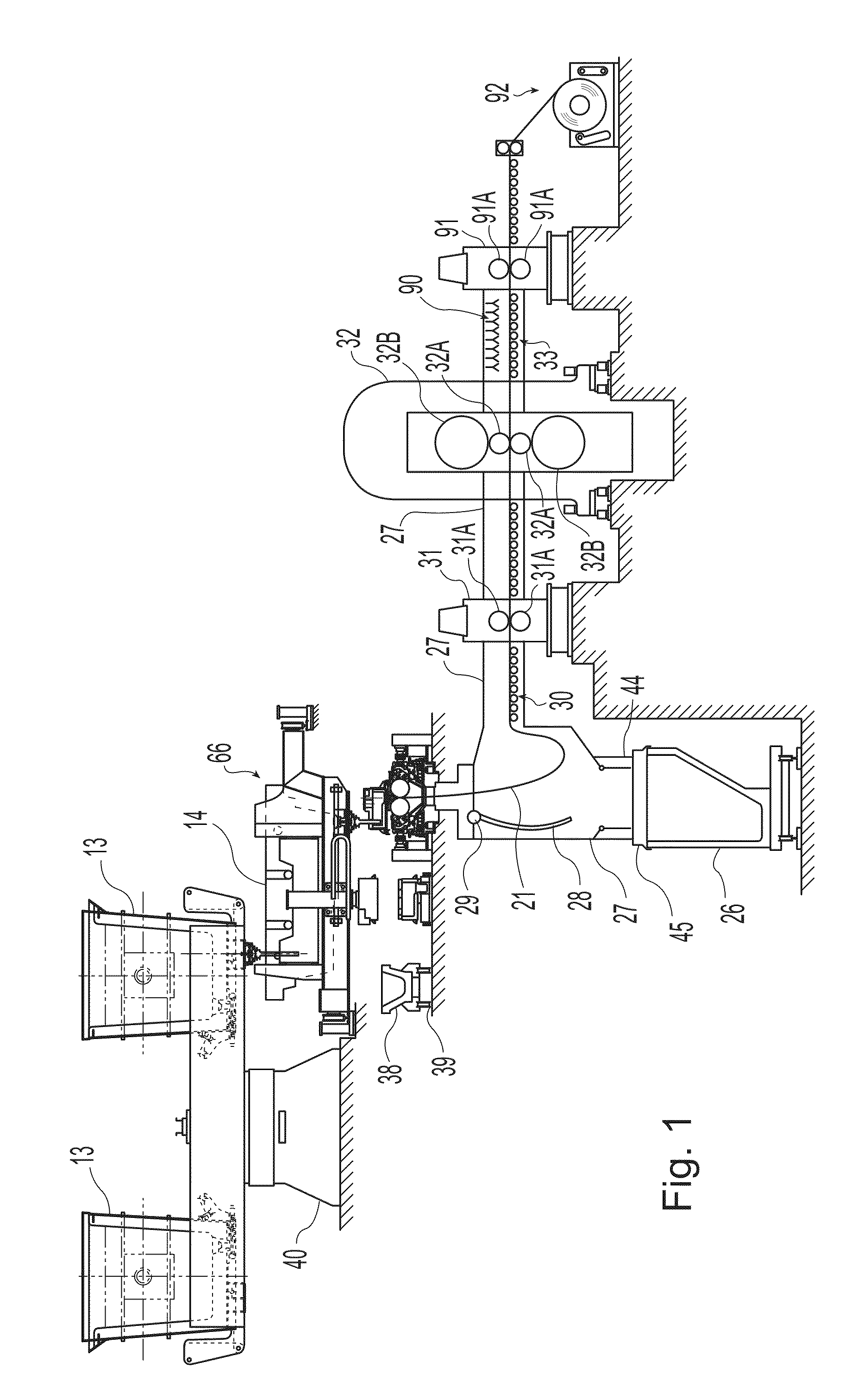
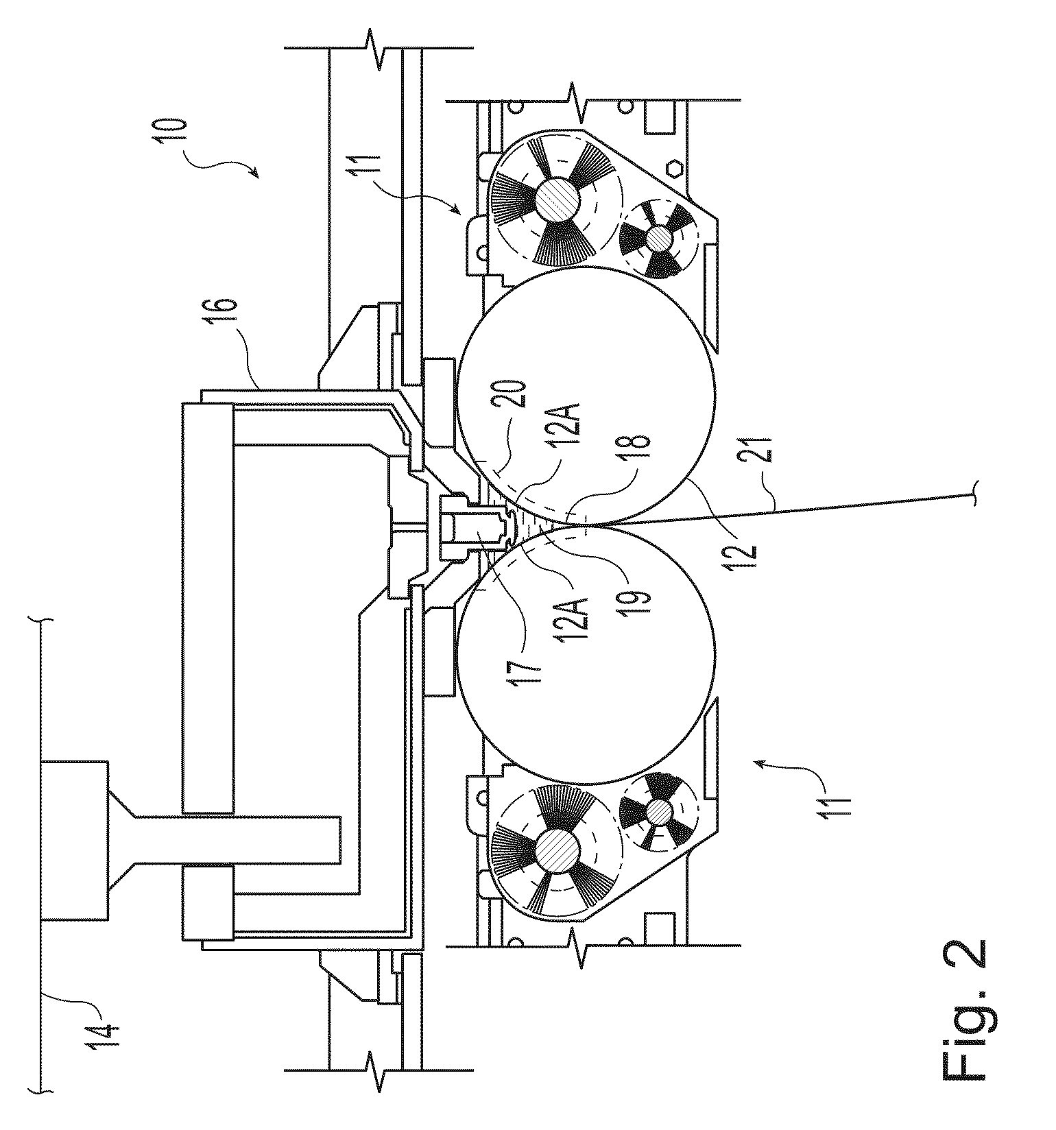
[0033]Referring now to the drawings, there is illustrated in FIGS. 1 and 2 a portion of a twin roll caster for continuously casting thin steel strip that comprises a main machine frame 10 that stands up from the factory floor and supports a roll cassette module 11 including a pair of counter-rotatable casting rolls 12 mounted therein. The casting rolls 12 having casting surfaces 12A laterally positioned to form a nip 18 there between. The casting rolls 12 are mounted in the roll cassette 11 for ease of operation and movement. The roll cassette facilitates rapid movement of the casting rolls ready for casting from a setup position into an operative casting position in the caster as a unit, and ready removal of the casting rolls from the casting position when the casting rolls are to be replaced. There is no particular configuration of the roll cassette that is desired, so long as it performs that function of facilitating movement and positioning of the casting rolls.

[0034]Molten meta...


PUM

PropertyMeasurementUnit
widthaaaaaaaaaa
widthaaaaaaaaaa
trough widthaaaaaaaaaa

Abstract

Apparatus for continuously casting metal strip includes a pair of counter-rotatable casting rolls laterally positioned to form a nip there between through which thin strip can be cast, a pair of confining side dams adjacent the ends of the casting rolls capable of confining a casting pool of molten metal supported on the casting rolls above the nip, each side dam having a surface capable of contacting the molten metal of the casting pool, with unraised portions and raised portions to form troughs with the unraised portions as base between the raised portion of the side dam and the casting surfaces of the casting rolls to guide the flow of molten metal, and a metal delivery system disposed above the nip and capable of discharging molten metal to form the casting pool supported on the casting rolls.

Description

CROSS-REFERENCE TO RELATED APPLICATIONS[0001]This application claims the benefit of U.S. Provisional Application No. 61 / 117,435 filed Nov. 24, 2008, the disclosure of which is incorporated herein by reference.BACKGROUND AND SUMMARY[0002]This invention relates in general to continuous casting of thin metal strip by a twin roll caster.[0003]In a twin roll caster molten metal is introduced between a pair of counter-rotated horizontal casting rolls that are cooled so that metal shells solidify on the moving roll surfaces, and are brought together at a nip between them to produce a solidified strip product delivered downwardly from the nip between the rolls. The term “nip” is used herein to refer to the general region at which the rolls are closest together. The molten metal may be poured from a ladle into a smaller vessel or series of smaller vessels from which it flows through a metal delivery nozzle or series of delivery nozzles (also called the “core nozzles”) located above the nip, ...

Claims


Application Information

Patent Timeline
Patent Type & Authority Applications(United States)
IPC IPC(8): B22D11/06
CPCB22D11/066B22D11/0622
Inventor MAHAPATRA, RAMA BALLAVBOWMAN, BRIAN E.
Owner NUCOR CORP
Why Eureka
Try Eureka