This helps you quickly interpret patents by identifying the three key elements:
Problems solved by technology
Method used
Benefits of technology
Problems solved by technology
[0005] The technical problem to be solved by the present invention is to provide an industrial microwave ultrasonic reactor, which overcomes the problems of the existing microwave ultrasonic reactor with small processing capacity, limited range of action of microwave and ultrasonic waves, and poor uniformity, and can shorten the chemical leaching time, Improve the purity of purified products and work efficiency
Method used
Image
Click on the blue label to locate the original text in one second.
Reading with bidirectional positioning of images and text.
Examples
Embodiment 1
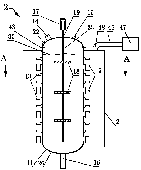
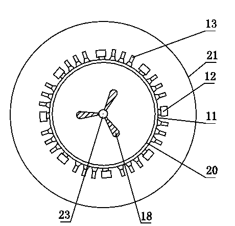
[0054] Such as figure 2 , image 3 , Figure 4 and Figure 5 As shown, a microwave ultrasonic reaction kettle 2 includes a kettle body 11, a microwave generating device, an ultrasonic generating device, a stirring device and a heat removal device. The top of the kettle body 11 is provided with a feed port 14, an exhaust port 15, and a viewing window 22 , a pressure relief valve and a pressure gauge (not shown in the figure), and a discharge port 16 is provided at the bottom of the kettle body 11 .
[0055] The kettle body 11 is a cylindrical reaction kettle, and the lining of the kettle body 11 is made of anti-corrosion wave-transmitting material, preferably a PTFE coating 20 with a thickness of 0.05-1 mm; Direct contact with leachate such as salt will cause equipment corrosion.
[0056] The microwave generating device includes 4 groups of horizontal arrangements, each group of 8 microwave units 12 arranged at intervals along the outer wall of the kettle body 11. The micr...
Embodiment 2
[0061] Such as Figure 6 , Figure 7 , Figure 8 and Figure 9 As shown, a microwave ultrasonic reaction kettle 2 of the present invention comprises a kettle body 11, a microwave generating device, an ultrasonic generating device, a stirring device, a heat removal device and a circulation pipe 26, and the top of the kettle body is provided with a feed port 14, an exhaust gas Port 15 and viewing window 22, and the bottom of kettle body 11 is provided with discharge port 16.
[0062] Still body 11 is a cylindrical reactor, as Figure 9 As shown, the lining of the kettle body is an anti-sticking and anti-corrosionbarrel 24 with a shape matching the inner wall of the kettle body 11 and a thickness of 3 to 30 mm in diameter, such as a PP (polypropylene) barrel. The wave-transparent glass wool 25 is arranged between the body 11, so that the anti-sticking and anti-corrosion barrel 24, the glass wool 25 and the kettle body 11 are closely attached to each other from the inside to ...
Embodiment 3
[0069] Such as Figure 10 , Figure 11 , Figure 12 and Figure 13As shown, a microwave ultrasonic reactor 2 of the present invention includes a kettle body 11, a microwave generating device, an ultrasonic generating device, a stirring device, a heat exhaust device, a baffle plate 29 and a return pipe I34, and the top of the kettle body is provided with a feed inlet 14. An exhaust port 15, a viewing window 22, and a discharge port 16 is provided at the bottom of the kettle body 11.
[0070] Such as Figure 11 As shown, the kettle body 11 is a cylindrical reaction kettle, and the inner lining of the kettle body 11 is a layer of PTFE coating 20 with a thickness of 0.05-3mm closely attached to the inner wall of the kettle body 11 .
[0071] The microwave generating device includes 4 groups of horizontal arrangements, each group of 8 microwave units 12 arranged at intervals along the outer wall of the kettle body 11. The microwave unit 12 is provided with a magnetron, a second...
PUM
Property
Measurement
Unit
power
aaaaa
aaaaa
wavelength
aaaaa
aaaaa
frequency
aaaaa
aaaaa
Abstract
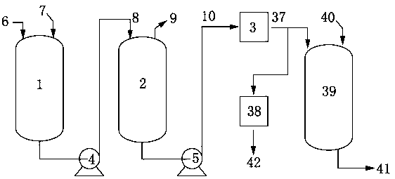
Disclosed is an industrial microwave ultrasonic reactor. The inner wall of the reactor is provided with a liner; a microwave generation device is composed of microwave units distributed over the outer sidewall of the reactor in a spaced manner, or of a microwave pipe provided outside the reactor and microwave units distributed over the microwave pipe in a spaced manner. One end of the microwave pipe is in communication with the bottom of the reactor via a connecting pipe I and the other end is in communication with the top of the reactor via a return pipe. A shield is provided outside the microwave generation device to space the microwave units apart from the outer space, with a heat removal device being provided outside the shield. The microwave generation device is composed of ultrasonic pulse units provided along the outer sidewall of the reactor in a spaced manner; there are 10 - 30 sets of ultrasonic pulse units provided from top to bottom, each set having 10 - 50 members and being distributed along the circumferential direction of the reactor, and a stirring shaft of a stirring device is fixed below a stirring motor and extends into the reactor. The present reactor can shorten the time for chemical leaching, improve the purity of a product extracted and increase operation efficiency.
Description
technical field [0001] The invention relates to the field of physical / chemical reactionengineering equipment, in particular to an industrial microwave ultrasonic reactor. Background technique [0002] Microwave is an electromagnetic wave with a wavelength between infrared and ultrasonic waves. Its wavelength is between 1 meter and 1 millimeter, and its frequency is 300MHz to 300KMHz. Microwave heating induces molecular polarization and dipole through the interaction between microwave and molecules. Rotation causes rapid movement between molecules, so microwave heating has a strong penetrating effect, reaching the inside of the material and causing the internal temperature of the material to rise rapidly, so that the internal components are released freely to achieve the purpose of removing or extracting components, which can greatly improve Reaction speed, reducing the activation energy of chemical reactions. When microwave encounters different media during transmission, d...
Claims
Application Information
Patent Timeline
Application Date:The date an application was filed.
Publication Date:The date a patent or application was officially published.
First Publication Date:The earliest publication date of a patent with the same application number.
Issue Date:Publication date of the patent grant document.
PCT Entry Date:The Entry date of PCT National Phase.
Estimated Expiry Date:The statutory expiry date of a patent right according to the Patent Law, and it is the longest term of protection that the patent right can achieve without the termination of the patent right due to other reasons(Term extension factor has been taken into account ).
Invalid Date:Actual expiry date is based on effective date or publication date of legal transaction data of invalid patent.

