Internal cooling system with insert forming nearwall cooling channels in an aft cooling cavity of an airfoil usable in a gas turbine engine

a gas turbine engine and cooling system technology, applied in the field of gas turbine engines, can solve the problems of consuming cooling air pressure, reducing cooling effectiveness, and less efficient use of cooling air, and achieve the effects of increasing the effectiveness of the internal cooling system, and enhancing the flow pattern

Inactive Publication Date: 2018-01-09
SIEMENS AG
View PDF43 Cites 3 Cited by
  • Summary
  • Abstract
  • Description
  • Claims
  • Application Information

AI Technical Summary

Benefits of technology

[0004]An airfoil for a gas turbine engine in which the airfoil includes an internal cooling system with one or more internal cavities having an insert contained therein that forms nearwall cooling channels having enhanced flow patterns is disclosed. The flow of cooling fluids in the nearwall cooling channels may be controlled via a plurality of cooling fluid flow controllers extending from the outer wall forming the generally hollow elongated airfoil. The cooling fluid flow controllers may be collected into spanwise extending rows. In at least one embodiment, the cooling fluid flow controllers may be positioned within a pressure side nearwall cooling channel and a suction side nearwall cooling channel that are both in fluid communication with a trailing edge channel. The trailing edge channel may also include cooling fluid flow controllers extending between the outer walls forming the pressure and suction sides, thereby increasing the effectiveness of the internal cooling system. The internal cooling system may include one or more bypass flow reducers extending from the insert toward the outer wall to direct the cooling fluids through the nearwall cooling channels created by the cooling fluid flow controllers, thereby increasing the effectiveness of the internal cooling system.
[0011]An advantage of the internal cooling system is that the cooling fluid flow controllers significantly increase the exposed surface area within the cooling system for better cooling system performance.
[0012]Another advantage of the internal cooling system is that the insert having the bypass flow reducers directs cooling fluids towards the outer wall to increase cooling rather than using a higher number of impingement holes in the insert, which would only increase the problems associated with cross flow.
[0013]Yet another advantage of the internal cooling system is that the bypass flow reducers effectively force more high speed cooling air into the zigzag flow channels formed by the multiple rows of cooling fluids flow controllers adjacent to the hot exterior walls of the airfoil.

Problems solved by technology

The cross flow can bend the impinging jets away from the impingement target surface and reduce the cooling effectiveness.
However, the greater the number of film cooling holes, the less efficient usage of cooling air is.
The impingement holes consume cooling air pressure and often pose a problem at the leading edge, where showerhead holes experience high stagnation gas pressure on the external surface.

Method used


Image

  • Internal cooling system with insert forming nearwall cooling channels in an aft cooling cavity of an airfoil usable in a gas turbine engine
  • Internal cooling system with insert forming nearwall cooling channels in an aft cooling cavity of an airfoil usable in a gas turbine engine
  • Internal cooling system with insert forming nearwall cooling channels in an aft cooling cavity of an airfoil usable in a gas turbine engine

Examples


Embodiment Construction

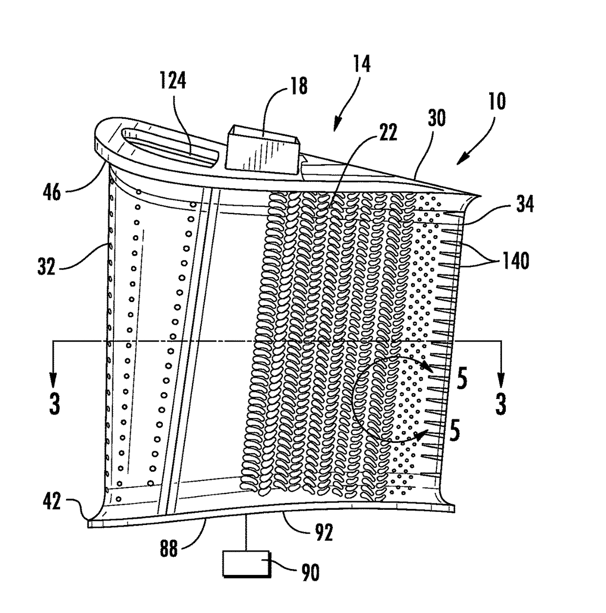
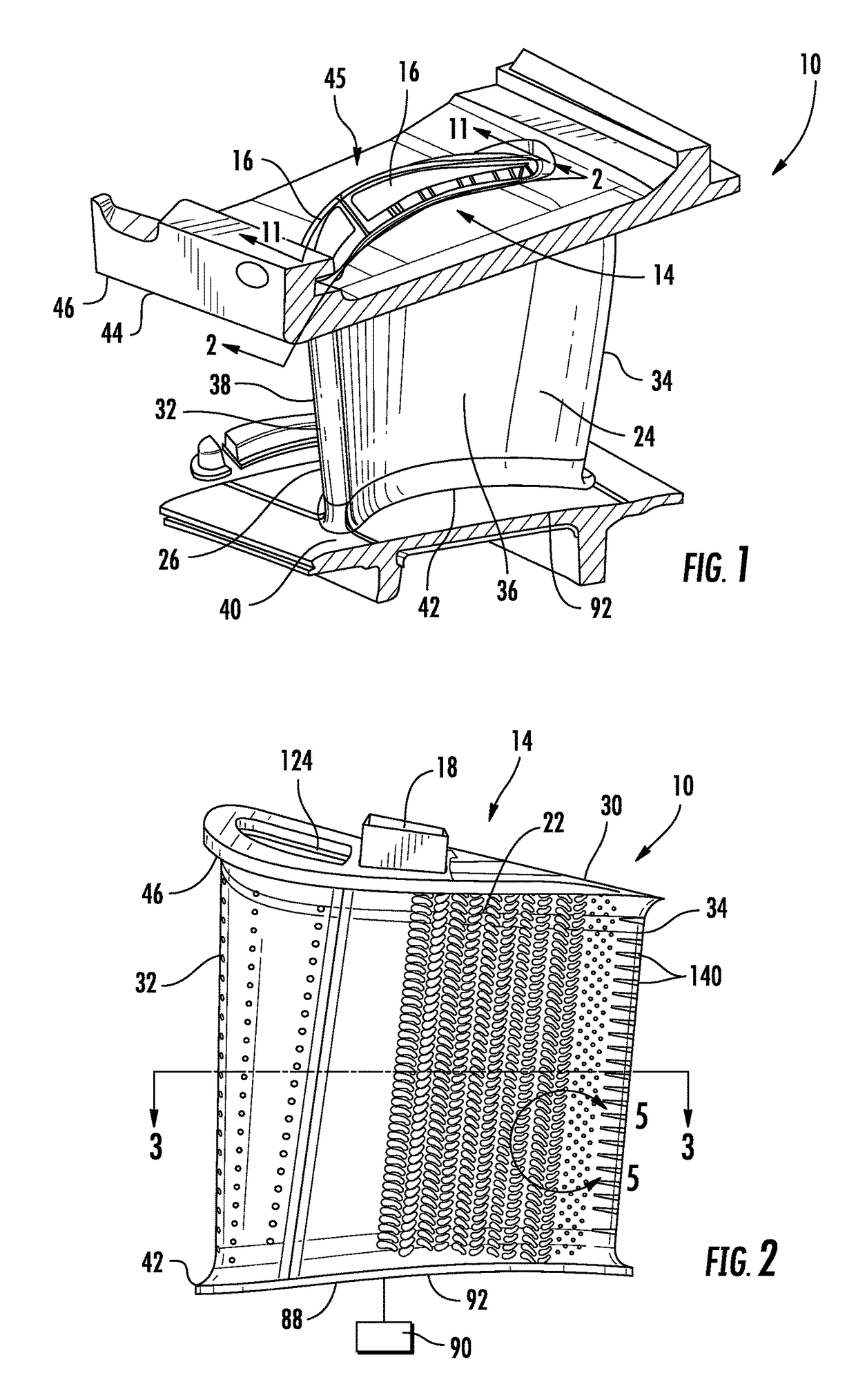
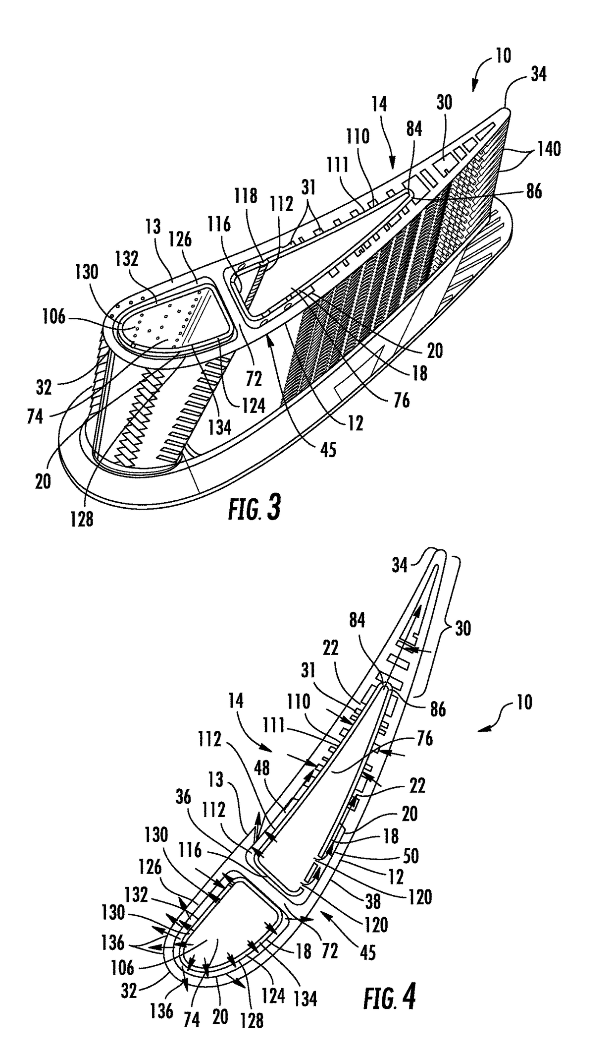
[0028]As shown in FIGS. 1-12, an airfoil 10 for a gas turbine engine in which the airfoil 10 includes an internal cooling system 14 with one or more internal cavities 16 having an insert 18 contained therein that forms nearwall cooling channels 20 having enhanced flow patterns is disclosed. The flow of cooling fluids in the nearwall cooling channels 20 may be controlled via a plurality of cooling fluid flow controllers 22 extending from the outer wall 24 forming the generally hollow elongated airfoil 26. The cooling fluid flow controllers 22 may be collected into spanwise extending rows 28. In at least one embodiment, the cooling fluid flow controllers 22 may be positioned within a pressure side nearwall cooling channel 48 and a suction side nearwall cooling channel 50 that are both in fluid communication with a trailing edge channel 30. The trailing edge channel 30 may also include cooling fluid flow controllers 22 extending between the outer walls 13, 12 forming the pressure and s...


PUM


Abstract

An airfoil (10) for a gas turbine engine in which the airfoil (10) includes an internal cooling system (14) with one or more internal cavities having an insert (18) contained within an aft cooling cavity (76) to form nearwall cooling channels having enhanced flow patterns is disclosed. The flow of cooling fluids in the nearwall cooling channels may be controlled via a plurality of cooling fluid flow controllers (22) extending from the outer wall (24) forming the generally hollow elongated airfoil (26). The cooling fluid flow controllers (22) may be collected into spanwise extending rows. In at least one embodiment, the cooling fluid flow controllers (22) may be positioned within a pressure side nearwall cooling channel (48) and a suction side nearwall cooling channel (50) that are both in fluid communication with a trailing edge channel (30). The trailing edge channel (30) may also include cooling fluid flow controllers (22) extending between the outer walls (12, 13) forming the pressure and suction sides.

Description

FIELD OF THE INVENTION[0001]This invention is directed generally to gas turbine engines, and more particularly to internal cooling systems for airfoils in gas turbine engines.BACKGROUND[0002]Typically, gas turbine engines include a compressor for compressing air, a combustor for mixing the compressed air with fuel and igniting the mixture, and a turbine blade assembly for producing power. Combustors often operate at high temperatures that may exceed 2,500 degrees Fahrenheit. Typical turbine combustor configurations expose turbine vane and blade assemblies to high temperatures. As a result, turbine vanes and blades must be made of materials capable of withstanding such high temperatures, or must include cooling features to enable the component to survive in an environment which exceeds the capability of the material. Turbine engines typically include a plurality of rows of stationary turbine vanes extending radially inward from a shell and include a plurality of rows of rotatable tur...

Claims


Application Information

Patent Timeline
Patent Type & Authority Patents(United States)
IPC IPC(8): F01D5/18
CPCF01D5/188F05D2260/20F05D2250/183F05D2220/32F01D5/189F05D2260/201F05D2240/127B22C9/10F01D9/065F05D2240/122F05D2260/202F05D2260/2214
Inventor LEE, CHING-PANGUM, JAE Y.PU, ZHENGXIANGABDULLAH, MOHAMEDSCHROEDER, ERICWAYWOOD, ANTHONY
Owner SIEMENS AG
Why Eureka
Try Eureka